
Disposable printing roller

Inactive Publication Date: 2005-03-24
ENGINERRED PLASTIC SOLUTIONS GRP
View PDF16 Cites 0 Cited by
  • Summary
  • Abstract
  • Description
  • Claims
  • Application Information

AI Technical Summary

Benefits of technology

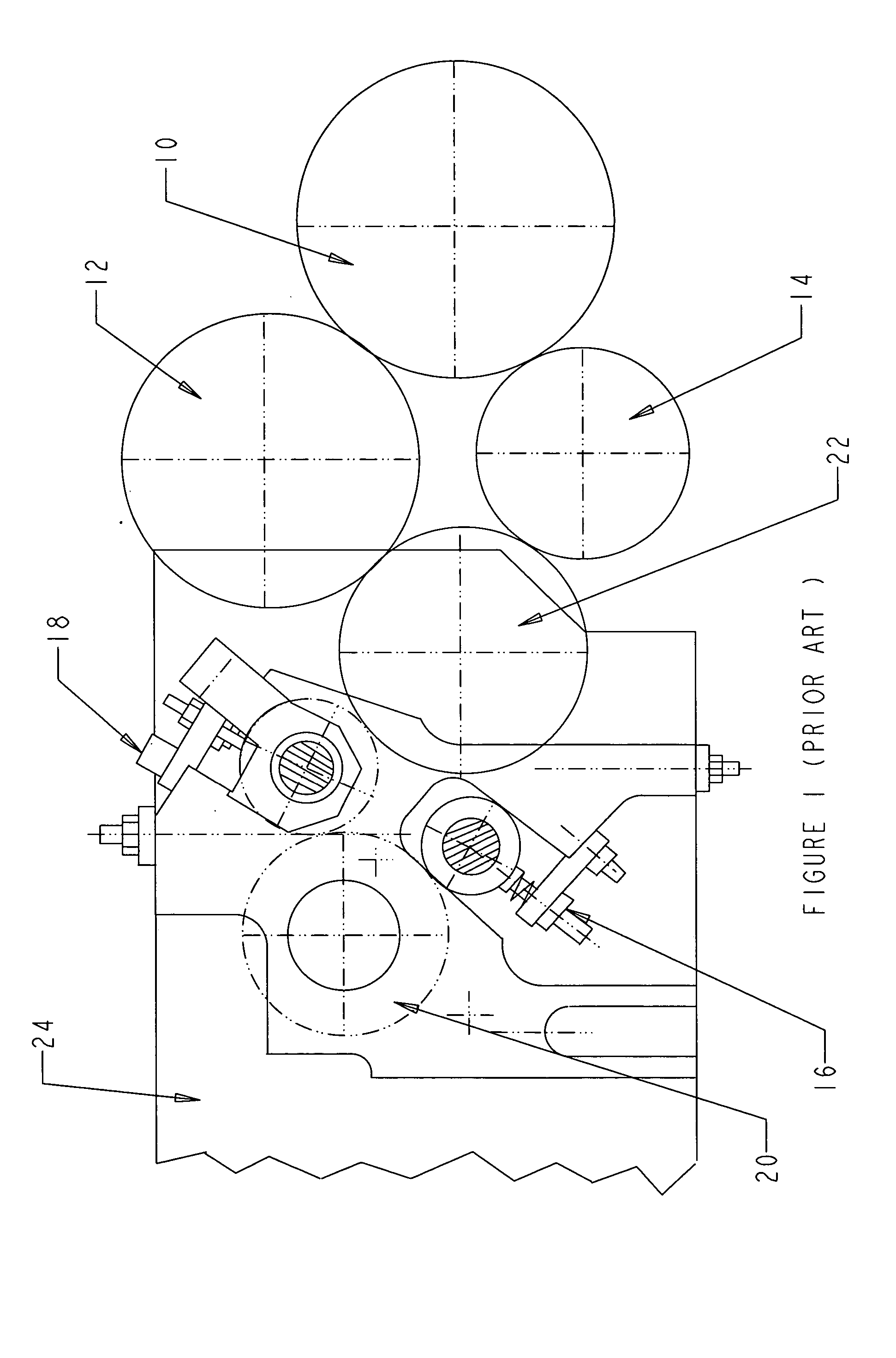
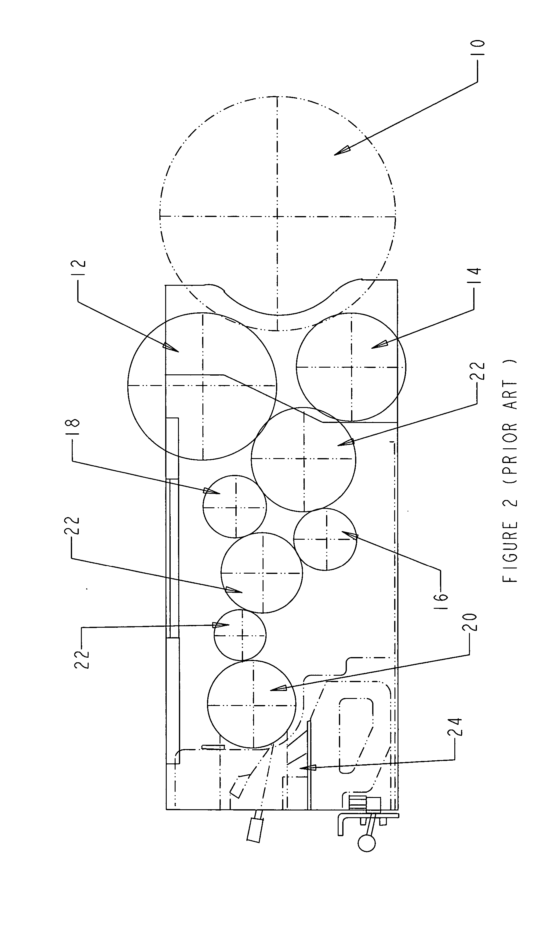
[0017] The present invention is directed to disposable printing rollers for the dry offset printing industry. More specifically, the present invention is designed for the plastic printing industry for printing cups, containers, buckets, lids, etc. The novel design incorporates the same strength and durability as present non-disposable solid core printing rollers without the high cost and maintenance while at the same time being a novel improvement over prior designs. The invention provides the ease of single use rollers at a similar cost of most resurfacing roller. The invention comes in different styles depending on the application and the printing press used.
[0019] Accordingly, one object of this invention is to provide an inexpensive disposable printing roller for the plastic dry offset printing industry for printing plastic cups, containers, buckets, lids, etc.
[0020] Another object of this invention is to provide a disposable printing roller to streamline the printing process by eliminating the need to have the roller resurfaced each time the rubber covering is worn.
[0021] A third object of this invention is to streamline the logistical management of the printing industry by not requiring and needing to inventory the rollers that need to be resurfaced, inventorying the resurfaced rollers and the requirement of a staging area for resurfaced rollers.
[0022] A fourth object of this invention is to have thermally press fit end caps that will not spin out under the shear stresses encountered with a typically dry offset printing press.
[0023] A fifth object of this invention is to have a printing roller that incorporates and combines the structural integrity of a solid core roller with the convenience and cost effectiveness of a hollow core roller.

Problems solved by technology

The machining process requires a great deal of time and manufacturing costs to complete.
The fact that the roller is made out of a solid block of material results in a high material cost for the roller.
Although hollow core rollers do not have the high material expense as solid core rollers, some hollow core rollers do have high machining costs required to machine the core and bearing units.
In addition, hollow core rollers can experience a phenomenon of the roller “spinning out” due to the high shear stresses encountered by a roller in a printing press.
Spinning out” occurs when the fit between the hollow core and the end plug fails due to the shear stress of the printing press causing the hollow core to “spin” around the end plug.
When a roller experiences a “spin out” quite often damage can occur to the roller, the rubber on the roller, the roller's bearings, the press, or a combination of the above.
When a “spin out” occurs, down time is encountered, as an operator needs to stop the press, change the roller and reset the press setup.
Typically the rubber is worn over several uses of the printing roller or by operator error.
Consequently, as the printing press operates, the rubber on the rollers becomes worn and will be required to be replaced, which is an expensive process.
The resurfacing of the roller is a significant cost.
In addition to the resurfacing house's fees and shipping cost, there are also administration costs and logistics related to the collecting, shipping, receiving and storing of the resurfaced printing rollers.
There is significant time and cost associated with the resurfaced rollers as one needs to store the rollers in a spare location and inventory each roller type.
Unfortunately, this is not always done because at the time a worn roller is removed from the press the operator is generally busy or simply forgets and the roller can be misplaced or potentially lost.
The above referenced work requires time and labor, both of which are an expense for the printer.
However, the keyway press fit device has several drawbacks.
First, there are costs involved with making the keyway end cap and keyways in the roller as one or both have to be milled or broached.
Second, the high shear stresses of a printing press are localized around the keys and not around the circumference of the connection in the fit.
Third, because of the localized stress points at the keys the latter are designed to and quite offer break off or become loose causing the same problems with the rollers “spinning out” and damaging other rollers and / or the rubber on any of the given rollers in the press.
Consequently, the keyway press fit designed rollers are not used in the dry offset printing industry due to the several inherent drawbacks to the design.
In addition, the novel thermal press fit eliminates the common problem of rollers “spinning out” during operation as encountered with the mentioned hollow core designs of the prior art as those designs only have an keyway press fit or a mechanical press fit, both of which are ineffective in a printing press.
This interference does not create a strong enough fit to withstand the shear stresses created in a dry offset printing press.
That is, the fit will fail and the inside of the roller will spin around the outer diameter of the end plug or journal causing numerous problems with the printing press operation and damage to the rollers in the press.
The same problem of the rollers “spinning out” is encountered with the keyway press fit as the keys will fail.

Method used


Image

  • Disposable printing roller
  • Disposable printing roller
  • Disposable printing roller

Examples


Embodiment Construction

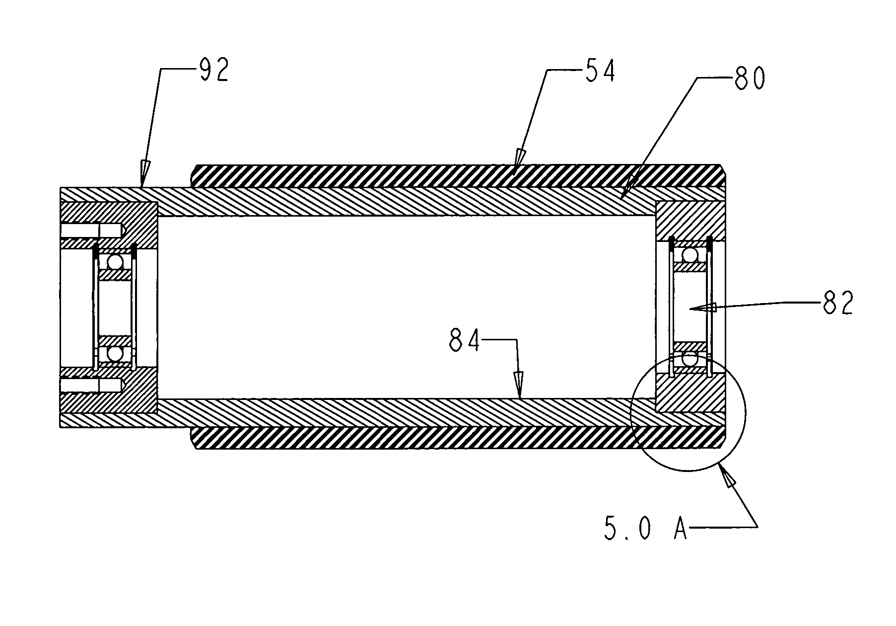
[0037] Referring to the Figures and more specifically FIGS. 6, 7 and 7A, the invention consists of a hollow core 50 made from a strong and inexpensive metal with the preferred embodiment being steel. The hollow core 50 may also be made out of aluminum. The hollow core 50 is cylindrical in shape and has an inner diameter and an outer diameter. There is an opening at each end of the hollow core 50. The hollow core 50 has an inside surface 70 and an outside surface 56. The hollow core 50 is cut to a desired length depending on the printing roller requirements.

[0038] The invention also consists of two end caps 52 that are designed to work in conjunction with the hollow core 50. There is a right end cap and a left end cap. Referring to FIG. 8 the end cap consists of a protrusion 62, a flange 64, an extension 66 and a journal 68 containing a slot 72. The protrusion 62 has an outer surface 90 and is specifically designed to engage with the inner surface 70 of the hollow core 50. The flang...


PUM


Abstract

The invention relates to printing rollers that are used in the dry offset printing industry. Presently there are no effective disposable printing rollers designed for use in printing presses used in the dry offset printing industry. The invention comes in different designs depending on the particular press involved. The invention can be manufactured and sold at a cost similar to the resurfacing costs of the present non-disposable printing rollers but is as structurally sound as a non-disposable printing roller. The invention provides the convenience of being disposable saving time and cost to the printer. The high administrative and logistic costs associated with resurfacing printing rollers are eliminated with the present invention. One need only use the disposable printing roller once and simply dispose of it once the roller is no longer useful.

Description

[0001] This application is a continuation-in-part of a U.S. application, application Ser. No. 10,327,478, filed on Dec. 20, 2002.BACKGROUND [0002] a) Field of the Invention [0003] This invention relates to the industry of printing rollers used in the dry offset printing industry. More specifically, the invention relates to printing rollers used in the plastic printing industry. The invention is a unique and effective disposable printing roller designed to replace the existing printing rollers in the industry that are presently non-disposable and replace the disposable printer rollers that are currently not effective. [0004] Presently there is a need in the plastic printing industry for an effective low cost and efficient disposable printing roller that performs in a dry offset printing press. Solid core printer rollers provide a strong structural roller but at a high manufacturing cost. On the other hand, a hollow core roller is less expensive to manufacture but is not as structural...

Claims


Application Information

Patent Timeline
IPC IPC(8): B41F13/10
CPCB41F13/10
Inventor LARSON, ERIK S.MANSFIELD, WILLIAM EDWARD JR.
Owner ENGINERRED PLASTIC SOLUTIONS GRP
Learn More