Inkjet printer

a technology of inkjet printers and inkjet printers, which is applied in the direction of printing, other printing apparatus, etc., can solve the problems of affecting the and consuming more time in the purging operation, so as to achieve good printing quality of inkjet printing

Active Publication Date: 2005-03-24
BROTHER KOGYO KK
View PDF5 Cites 36 Cited by
  • Summary
  • Abstract
  • Description
  • Claims
  • Application Information

AI Technical Summary

Benefits of technology

[0007] In order to obtain an excellent image, not only is it necessary to prevent the viscosity of ink in nozzles from increasing, but it is also necessary to protect each meniscus properly. The meniscus means the surface where ink in each nozzle of the recording head borders on the atmosphere. The meniscus has influence on the flying condition of the ink. Accordingly, when the meniscus is broken, the ink cannot be ejected satisfactorily. As a result, the printing quality is degraded. The meniscus can be restored to its proper condition by the aforementioned purging operation. However, the amount of ink discharged in the purging operation is larger than that in the flushing operation. In addition, it takes more time in the purging operation.
[0010] The invention provides an inkjet printer in which a hand is prevented from directly touching a recording head to smear the hand, so that the printing quality can be kept good.
[0012] With this configuration, a hand is prevented from touching a recording head directly to smear the hand at the time of maintenance for solving a paper jam, so that the printing quality of the inkjet printer can be kept good.

Problems solved by technology

As a result, the printing quality is degraded.
However, the amount of ink discharged in the purging operation is larger than that in the flushing operation.
In addition, it takes more time in the purging operation.
However, the hand, the paper, or the like, may touch the recording head, particularly the ejection surface so that menisci are broken.
Thus, there occurs another problem that paper conveyed in the paper conveyance path is contaminated with the transferred ink so that the printing quality is degraded.

Method used


Image

  • Inkjet printer
  • Inkjet printer
  • Inkjet printer

Examples


embodiment 1

[0026] [Embodiment 1]

[0027] A preferred embodiment of the invention will be described below with reference to the drawings.

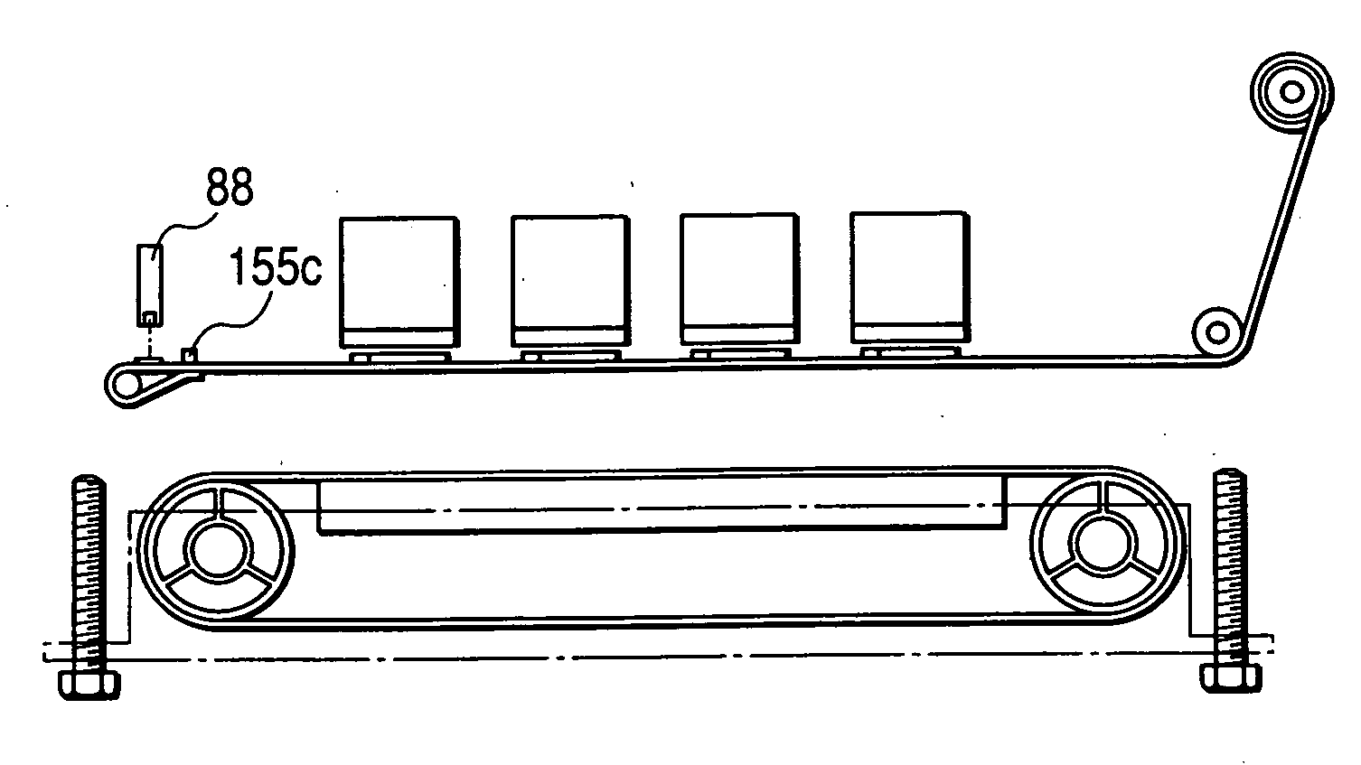
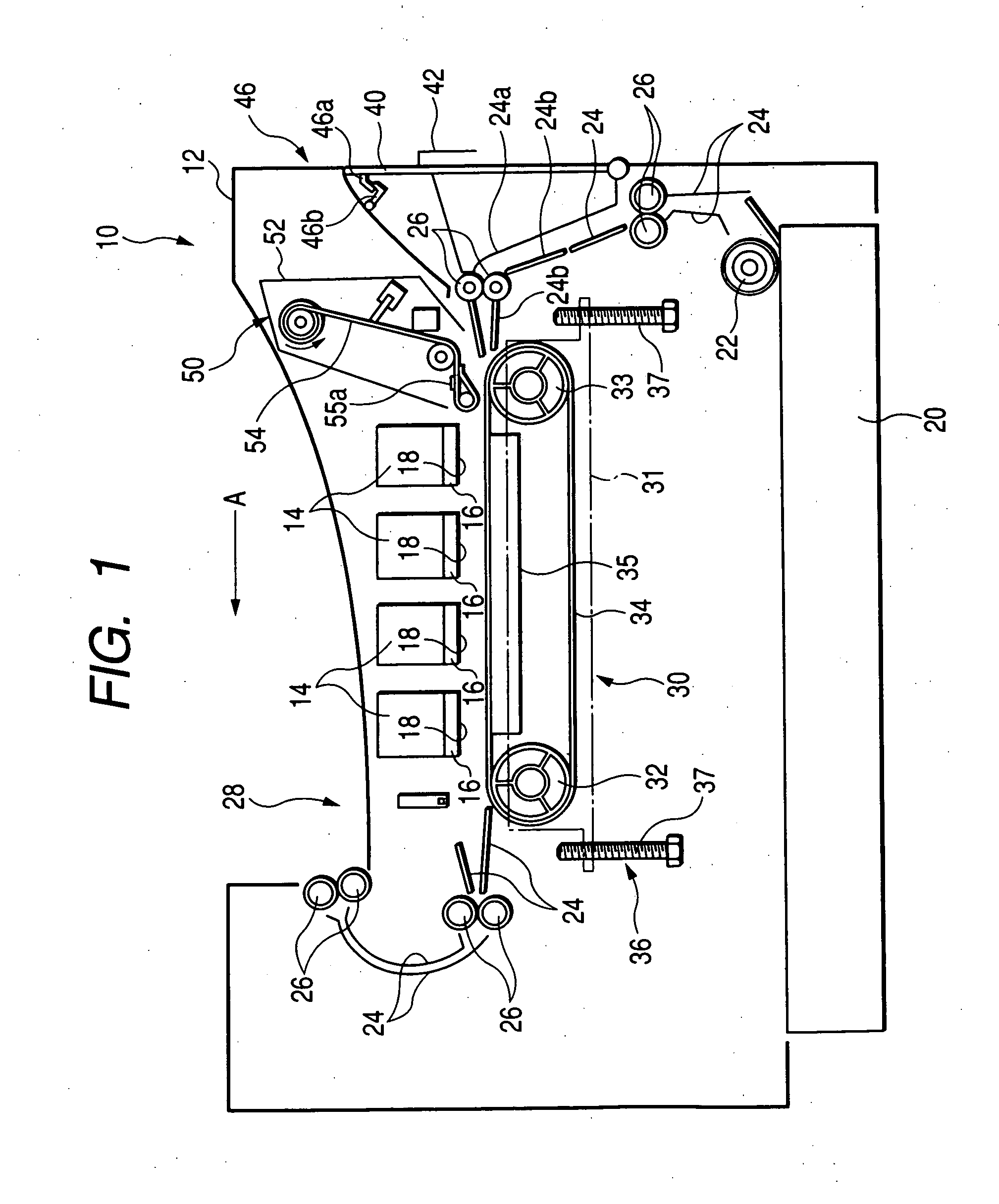
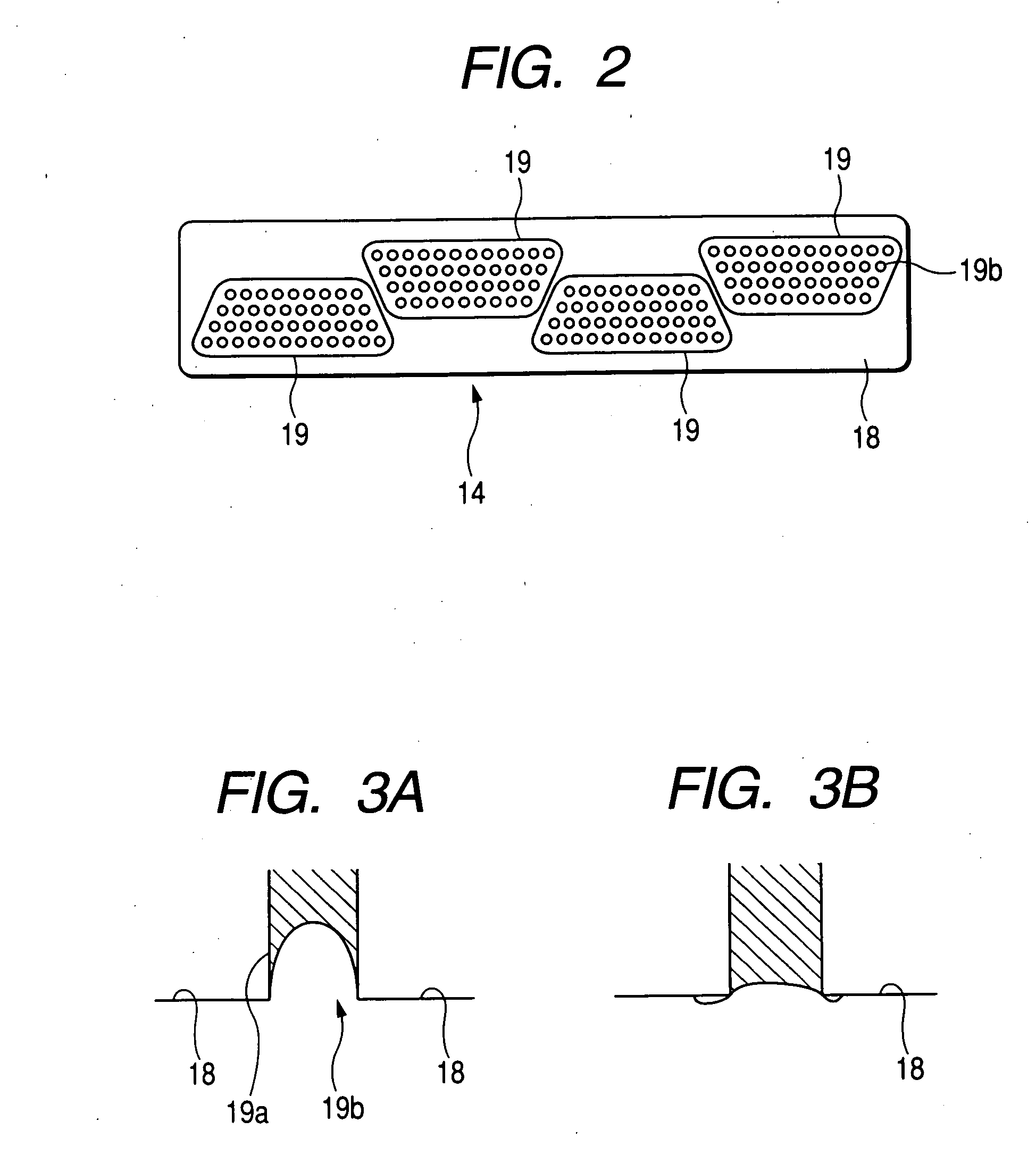
[0028] First, an inkjet printer according to Embodiment 1 of the invention will be described with reference to FIGS. 1-3B. FIG. 1 is a side view showing the overall configuration of an inkjet printer 10 according to this embodiment. FIG. 2 is a plan view of a recording head 14, when viewed from an ejection surface 18. FIGS. 3A and 3B are explanatory views showing the conditions of a head body 16 near an ejection port 19b.

[0029] The inkjet printer 10 shown in FIG. 1 is a line-head-type color inkjet printer having four line-type recording heads 14 in a housing 12 of the printer. That is, the inkjet printer 10 is a line-printing-type inkjet printer in which the positions of the recording heads 14 are fixed at the time of printing and which forms an image on a printing medium conveyed by a conveyance unit 30, which will be described later. A paper tray 20 is provi...

embodiment 2

[0077] [Embodiment 2]

[0078] Next, another embodiment of the invention will be described with reference the drawings. Incidentally, description on similar configurations to those in Embodiment 1 will be omitted here. In addition, constituent parts similar to those in Embodiment 1 are denoted by the same reference numerals correspondingly, and a shutter in this embodiment will be referred to as “shutter 154”. FIGS. 9A and 9B are views of the shutter 154 according to this embodiment. FIG. 9A is a plan view of the shutter 154, when viewed from the facing surface, and FIG. 9B is a side view of the shutter 154, when viewed from the arrow B direction in FIG. 9A.

[0079] The shutter 154 in Embodiment 2 has a configuration in which contact preventing members for preventing the shutter 154 from contacting with the ejection ports are provided on a base sheet 154b instead of the water repellent sheet 54a of Embodiment 1.

[0080] As shown in FIGS. 9A and 9B, in the shutter 154, the base sheet 154b...


PUM


Abstract

An inkjet printer includes a recording head, a conveyance mechanism, a shutter, a storage portion, and a moving mechanism. The recording head includes an ejection surface in which an ejection port for ejecting ink is defined. The conveyance mechanism conveys a printing medium while the printing medium is facing the ejection surface. The shutter covers the ejection surface. The storage portion stores the shutter. The moving mechanism moves the shutter from the storage portion to a facing position while the shutter is separate from the ejection surface. The shutter faces and covers the ejection surface at the facing position.

Description

BACKGROUND OF THE INVENTION [0001] 1. Field of the Invention [0002] The present invention relates to an inkjet printer for ejecting ink from nozzles of a recording head onto a printing medium so as to form an image. [0003] 2. Description of the Related Art [0004] In the related art, inkjet printers that execute printing by ejecting very small ink droplets from a plurality of nozzles provided in a recording head are classified into so-called serial head type printers and so-called line head type printers. Each of the serial head type printers executes printing by the combination of a main-scanning-direction moving operation for ejecting ink while moving a recording head in a main scanning direction (paper width direction) and a sub-scanning-direction moving operation for moving paper in a sub-scanning direction. On the other hand, each of the line head type printers includes a line head having a printable width corresponding to the paper width of paper as a printing medium. In the li...

Claims


Application Information

Patent Timeline
Patent Type & Authority Applications(United States)
IPC IPC(8): B41J2/165B41J29/02B41J2/01
CPCB41J29/02B41J2/165
Inventor TAKAGI, OSAMUOKAMOTO, TSUGIO
Owner BROTHER KOGYO KK
Why Eureka
Try Eureka