Ink jet printer applying different voltage pulses in actuator

a technology of actuators and voltage pulses, which is applied in the direction of printing, inking apparatus, other printing apparatus, etc., can solve the problems of ink droplets not being stably discharged from the nozzle, ink consumption, etc., to prevent the viscosity of ink from increasing, avoiding ink consumption, and preventing the effect of ink viscosity

Active Publication Date: 2010-04-13
BROTHER KOGYO KK
View PDF14 Cites 5 Cited by
  • Summary
  • Abstract
  • Description
  • Claims
  • Application Information

AI Technical Summary

Benefits of technology

[0007]Ink is consumed when this discharge flushing is performed. In order to avoid this ink consumption, the present inventors considered adopting a technique termed non-discharge flushing wherein an increase in the viscosity of the ink within the nozzle is prevented without ink being consumed. In non-discharge flushing, the actuator is driven such that ink droplets are not discharged from the nozzle, and a pressure wave is generated in the ink within the pressure chamber and the nozzle. The ink is agitated. It is thus possible to prevent the viscosity of the ink from increasing.
[0008]The present inventors discovered that the efficiency of non-discharge flushing is improved by increasing the amplitude of the ink pressure wave. The amplitude of the ink pressure wave increases when the energy applied to the ink within the nozzle is increased. The present inventors discovered that it is possible to increase the energy applied to the ink within the nozzle by increasing the expanding and contracting velocity of the piezoelectric element of the actuator and increasing the vibration of the actuator. The expansion and contraction velocity of the piezoelectric element can be increased by increasing the amount of voltage change during a leading edge period (or a trailing edge period) of a voltage pulse applied to a first electrode (the amount of voltage change is a value wherein the amount of voltage change is divided by the period concerned, and will be termed ‘voltage change’ below). However, if the voltage change of the voltage pulse is also increased in the case where printing is to be performed by discharging ink from the nozzle, the ink droplet is not stably discharged from the nozzle. There is a range of voltage change suitable for discharging the ink droplet stably from the nozzle. Consequently, it is preferred that there is not an increase in the voltage change that is applied when printing is to be performed. To deal with this, the present inventors developed a novel technique whereby non-discharge flushing can be performed effectively without having an adverse effect on printing.
[0012]With this ink jet printer, it is possible to adopt the first voltage pulse that maintains a voltage change that allows the ink droplet to be discharged stably. That is, the voltage change of the first voltage pulse is set to be a value in which the ink droplet can be discharged stably. Printing can consequently be performed by ink droplets that are discharged stably. The voltage change of the second voltage pulse is greater than the voltage change of the first voltage pulse. As a result, when non-discharge flushing is performed by means of the second voltage pulse, the expansion and contraction velocity of the piezoelectric element of the actuator can be made greater than the velocity used for printing. In this ink jet printer, it is possible to increase the energy applied by the actuator to the ink within the nozzle during non-discharge flushing. Non-discharge flushing can consequently be performed efficiently.

Problems solved by technology

Ink is consumed when this discharge flushing is performed.
However, if the voltage change of the voltage pulse is also increased in the case where printing is to be performed by discharging ink from the nozzle, the ink droplet is not stably discharged from the nozzle.

Method used


Image

  • Ink jet printer applying different voltage pulses in actuator
  • Ink jet printer applying different voltage pulses in actuator
  • Ink jet printer applying different voltage pulses in actuator

Examples


Embodiment Construction

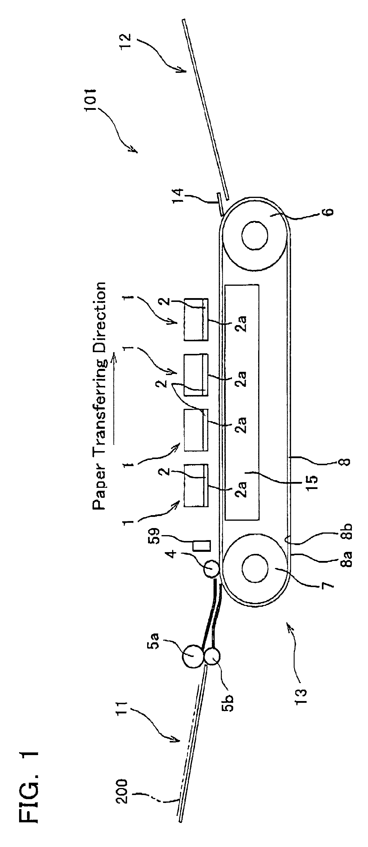
[0022]A suitable embodiment of the present invention will be described below with reference to the figures. FIG. 1 shows an outline side view of the entire configuration of an ink jet printer 101 (hereafter referred to as printer 101). As shown in FIG. 1, the printer 101 is a color ink jet printer that has four ink jet heads 1. In this printer 101, a paper feeding part 11 is on the left, and a paper discharge part 12 is on the right.

[0023]A paper transferring path for transferring paper (a print medium) 200 from the paper feeding part 11 toward the paper discharge part 12 is formed within the printer 101. A pair of transfer rollers 5a and 5b is disposed at a downstream side, in the direction of paper transferring of the paper feeding part 11. The pair of transfer rollers 5a and 5b transfers the paper 200 from the paper feeding part 11 toward the right. A belt transferring mechanism (paper transferring mechanism) 13 is disposed in a central portion of the paper transferring path. The...


PUM


Abstract

An ink jet printer is provided with a passage unit, an actuator, and a pulse applying device. The passage unit comprises a nozzle, a pressure chamber, and an ink passage located between the nozzle and the pressure chamber. The actuator faces the pressure chamber and comprises a first electrode, a second electrode to which a reference potential can be applied, and a piezoelectric element located between the first electrode and the second electrode. The pulse applying device is capable of applying a first voltage pulse to the first electrode such that the nozzle discharges an ink droplet, and a second voltage pulse to the first electrode such that the nozzle does not discharge the ink droplet. A voltage change on a leading edge and / or a trailing edge of the second voltage pulse is greater than a voltage change on a leading edge and / or a trailing edge of the first voltage pulse.

Description

CROSS-REFERENCE TO RELATED APPLICATION[0001]This application claims priority to Japanese Patent Application No. 2006-142293, filed on May 23, 2006, the contents of which are hereby incorporated by reference into the present application.BACKGROUND OF THE INVENTION[0002]1. Field of the Invention[0003]The present invention relates to an ink jet printer that performs printing by discharging ink droplets.[0004]2. Description of the Related Art[0005]An ink jet printer is provided with an ink jet head. A normal ink jet head has a passage unit and an actuator. The passage unit comprises a nozzle, a pressure chamber, and an ink passage located between the nozzle and the pressure chamber. The nozzle discharges ink droplets. The actuator applies pressure (discharging energy) to the ink within the pressure chamber by changing the volume of the pressure chamber. A normal actuator comprises a first electrode, a second electrode to which a reference potential is to be applied, and a piezoelectric ...

Claims


Application Information

Patent Timeline
Patent Type & Authority Patents(United States)
IPC IPC(8): B41J29/38B41J2/45
CPCB41J2/04541B41J2/04581B41J2/04588B41J2/04596B41J2/14209B41J2202/20B41J2002/14217B41J2002/14225B41J2002/14459B41J2002/14491
Inventor IWAO, NAOTOSAKAIDA, ATSUO
Owner BROTHER KOGYO KK
Why Eureka
Try Eureka