Device that appends a recognition point for image joining to the extracted image and a recognition element thereof

Inactive Publication Date: 2005-03-24
MICROTEK INT
View PDF4 Cites 3 Cited by
  • Summary
  • Abstract
  • Description
  • Claims
  • Application Information

AI Technical Summary

Benefits of technology

[0008] The main and first object of the invention is to provide a device that appends a recognition point for image joining to an extracted image obtained from segmented image extractions so that a clear and identifiable positioning mark can be automatically appe

Problems solved by technology

If, however, the image-joining technique is not g

Method used


Image

  • Device that appends a recognition point for image joining to the extracted image and a recognition element thereof
  • Device that appends a recognition point for image joining to the extracted image and a recognition element thereof
  • Device that appends a recognition point for image joining to the extracted image and a recognition element thereof

Examples


Embodiment Construction

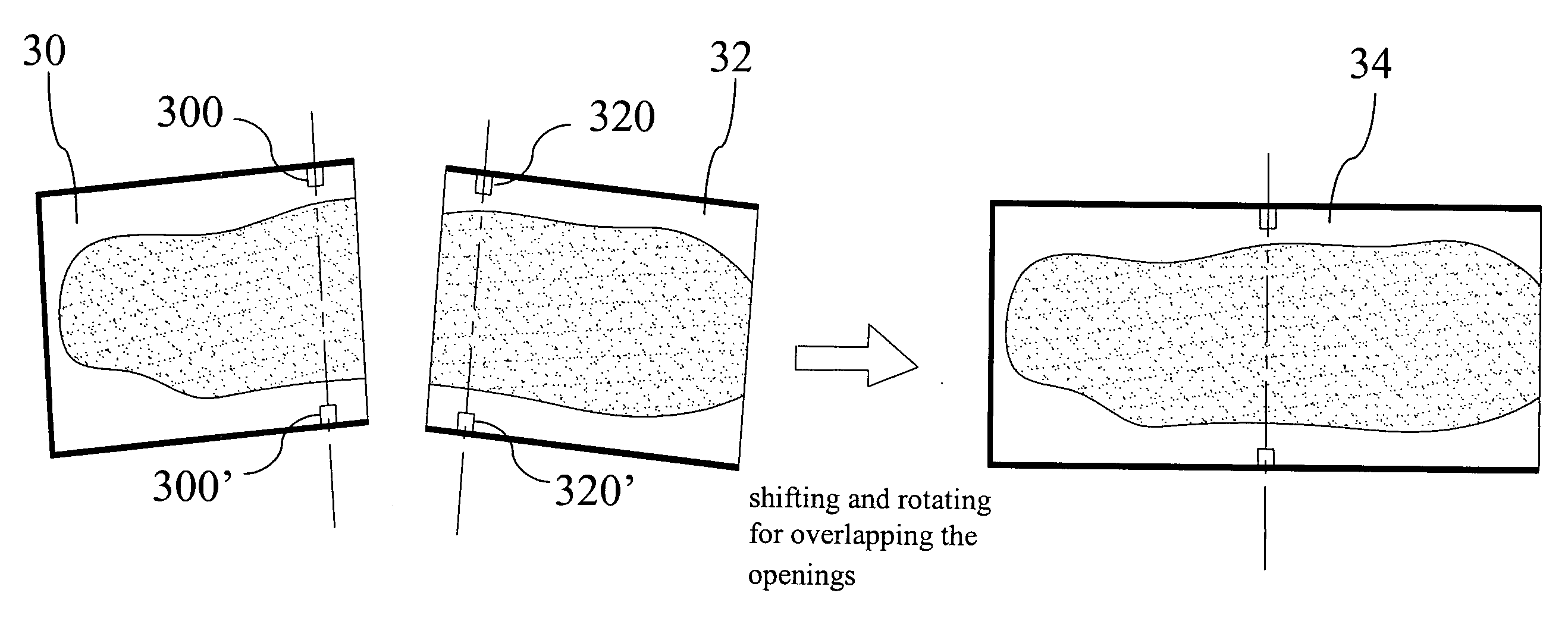
[0024] The invention is to automatically append an recognition mark to each extracted image when the image of an object is extracted by segmented extractions so that the recognition mark can be used as a referential benchmark for alignment during the image joining, and that the segmented images can be joined together rapidly and precisely according to the referential benchmark.

[0025] To implement the recognition mark appending operation, the invention allows the recognition mark for image joining to be directly formed in an opening shape on the image-extraction holding device, as shown in FIG. 4. FIG. 4 is a schematic diagram showing the structure of the image-extraction holding device of the invention. Referring to FIG. 4, an image-extraction holding device 20 is to provide a plurality of holding slots 24 on a holding platform 22. Each holding slot 24 is for accommodating and fastening the object to be image-taken. Besides, two positioning slots 26 are provided at one sidewall of ...


PUM


Abstract

The invention provides a device that appends a recognition point for image joining to the extracted image and a recognition element thereof. The device is to provide a plurality of holding slots on a holding platform. Besides, a plurality of positioning slots is provided at the sidewall of each holding slot so that the holding slot can accommodate and fasten an object to be image-taken. Then, when the image of the object is extracted by the segmented extractions, the image of the positioning slot can also be extracted so as to obtain an image with a recognition mark. Thus, the recognition mark can be used as a benchmark for image joining in order to obtain a whole image of the object. Moreover, the recognition element is to provide a positioning opening concavely at the side edge of a sheet-body, and the positioning opening is tiny. Therefore, the invention can achieve an effect of easy, rapid, and precise image joining.

Description

BACKGROUND OF THE INVENTION [0001] 1. Field of the Invention [0002] The invention relates to a device applied to image extractions and, more particularly, to a device that appends a recognition mark to an extracted image so that the recognition mark can be used as a referential benchmark for image alignment when joining images. [0003] 2. Description of the Related Art [0004] To scan an image of raw data (such as a photograph, a negative, or a slide) by a scanner or to take a picture of the data by a digital camera and make the image or the picture into an image file has become a common method for digital filing and archiving. [0005] On the other hand, in respond to a specific scanning of a light transmitting film—for instance, a positive film, a negative film, or a slide film—a platform scanner and a film scanner have been introduced for use. Particularly, these scanners can see through an object and scan various films. Among these scanners, the film scanner is designed for scanning...

Claims


Application Information

Patent Timeline
IPC IPC(8): G06K9/36H04N1/04
CPCH04N1/04H04N2201/0422H04N2201/0406H04N2201/0404
Inventor CHIEN, SHIH-HUNGFAN, PING-JUNG
Owner MICROTEK INT
Why Eureka
Try Eureka