Fuel supply for direct injected engine

Inactive Publication Date: 2001-04-10
SANSHIN KOGYO CO LTD
View PDF8 Cites 33 Cited by
  • Summary
  • Abstract
  • Description
  • Claims
  • Application Information

AI Technical Summary

Problems solved by technology

Electric pumps are not totally capable of supplying such high pressures.
However, in connection with outboard motors, the direct injection system causes problems in other aspects.
Because of frequent use under high load and low speed conditions, engines for the outboard motors consume a large amount of fuel relative to other engines such as automobile engines.
However, redevelopment of such a fuel pump is not much advantageous because it could be costly.
Procurement of it from parts suppliers might be more difficult because this kind of fuel pump requires special specifications.
In either case, if possible, a new fuel pump would be too bulky for being placed in a small space around the engine surrounded by a protective cowling and in addition it would take much time for the fuel pump to obtain reliability on components and parts.
In addition, only very small space is remained for employing new components around the engine that is surrounded by a cowling.
Ac

Method used


Image

  • Fuel supply for direct injected engine
  • Fuel supply for direct injected engine
  • Fuel supply for direct injected engine

Examples


Embodiment Construction

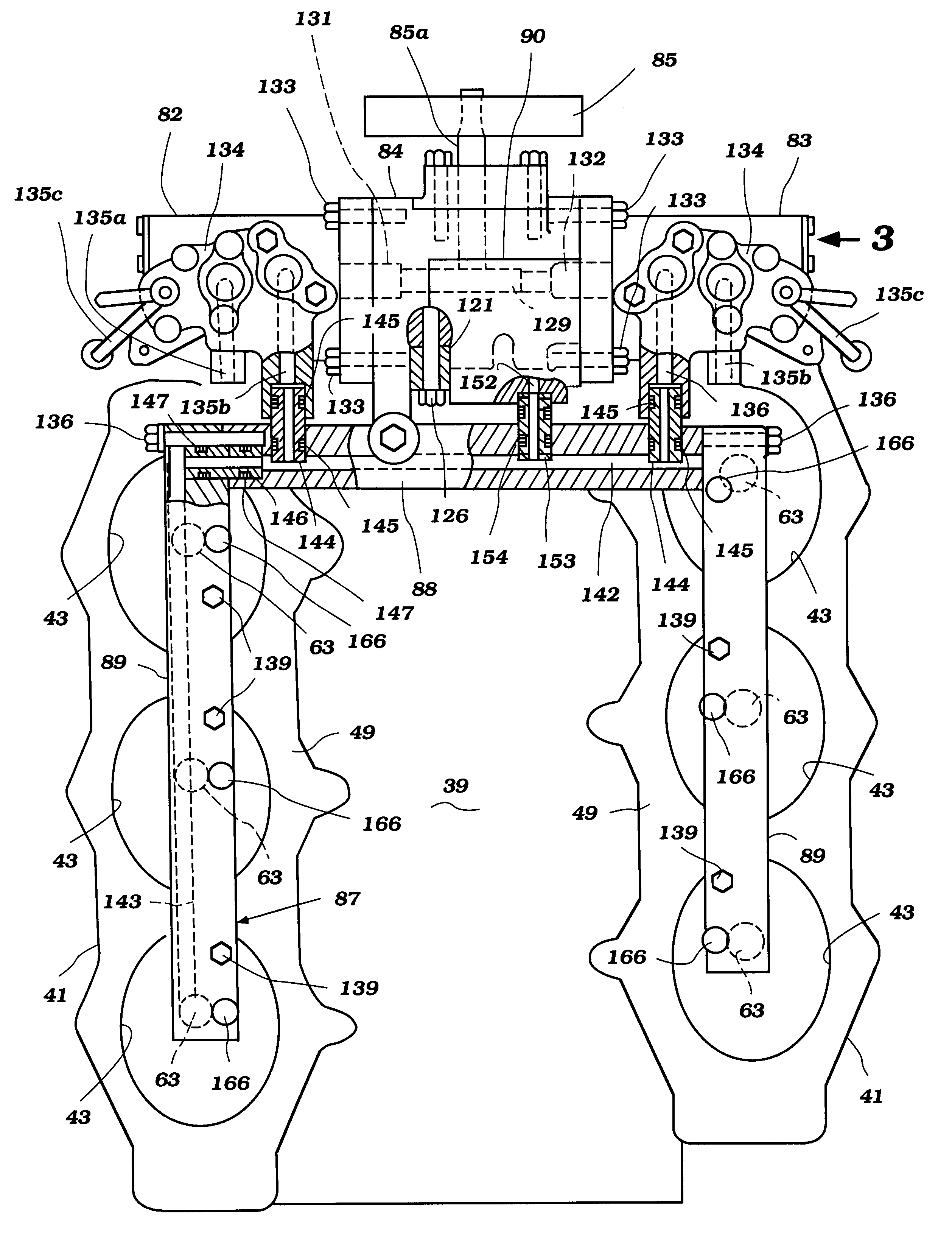
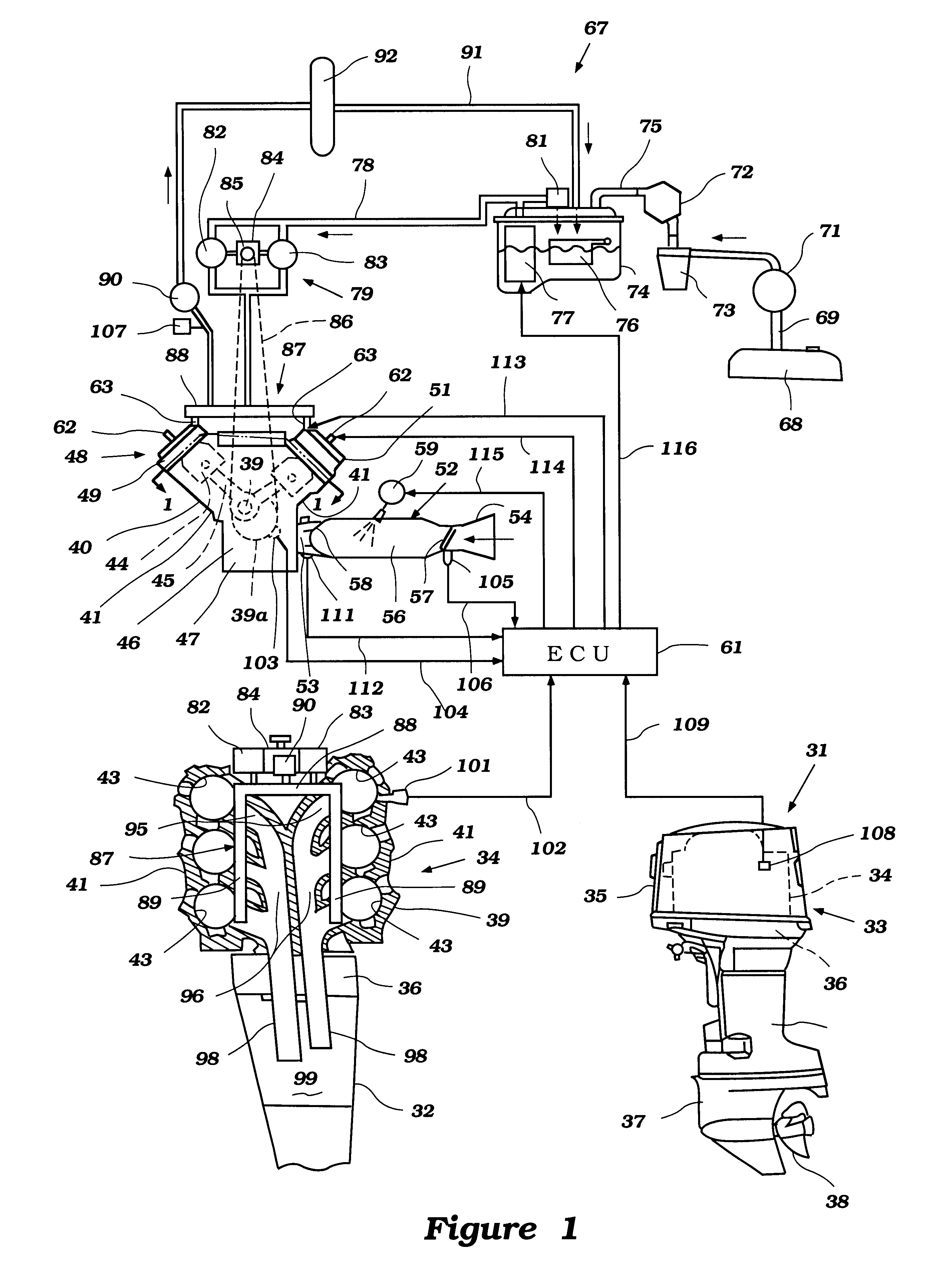
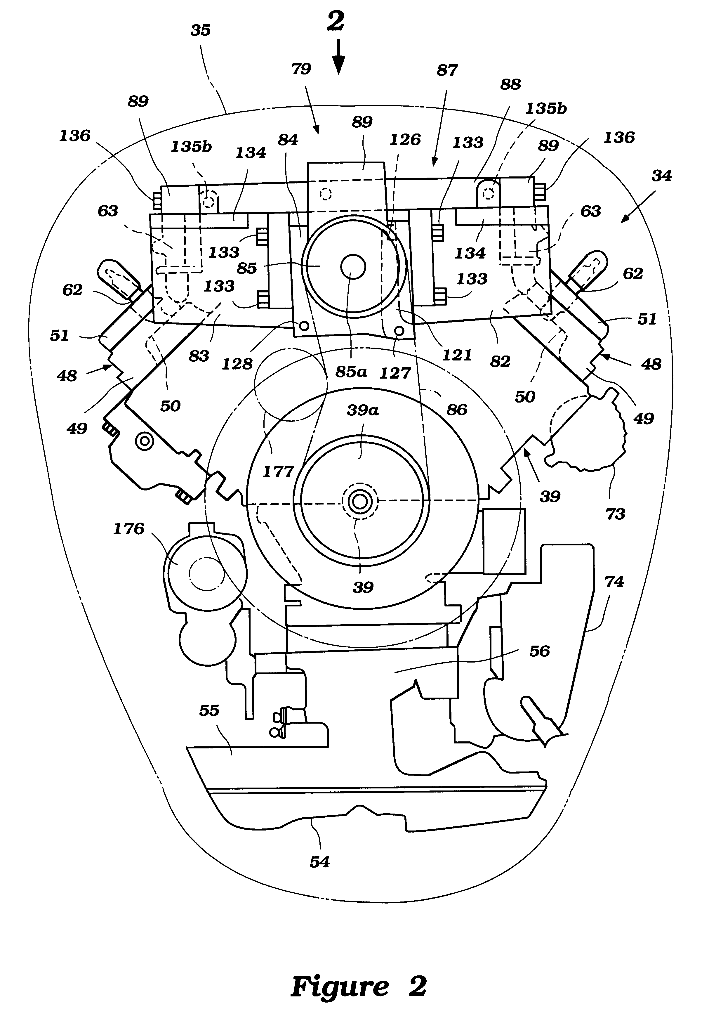
The general overall environment in which the invention is practiced and certain details of the engines will be described primarily by reference to FIG. 1 and additionally to FIGS. 2 through 7.

In the lower-right hand view of the FIG. 1, an outboard motor constructed and operated in accordance with an embodiment of the invention is depicted in side elevational view and is identified generally by the reference numeral 31.

The entire outboard motor 31 is not depicted in that the swivel bracket and clamping bracket that are associated with the driveshaft housing, indicated generally by the reference numeral 32, are not illustrated. This is because these components are well known in the art and the specific method by which the outboard motor 31 is mounted to the transom of an associated watercraft is not necessary to permit those skilled in the art to understand or practice the invention.

The outboard motor 31 includes a power head, indicated generally by the reference numeral 33, that is p...


PUM


Abstract

An improved fuel supply system for a direct injected engine accommodated in outboard motors includes a pump drive mechanism, instead of a camshaft, for driving a high pressure fuel pump. A pair of the high pressure fuel pumps is applied in one embodiment and a single one is applied in another embodiment. A pulsation damper is further provided for smoothing output of the fuel pump. The pump drive mechanism is unified with a fuel supply conduit, which has a plurality of fuel injectors, for increasing rigidity of components and affixed to the cylinder body of the engine. Openings on the cylinder head of the engine for accommodating the fuel injectors are larger than the injectors so that accumulated tolerances are absorbed by the gap made between the opening and the injector.

Description

1. Field of the InventionThis invention relates to a fuel injected system for a direct injected engine and more particularly to an improved fuel supply arrangement for an outboard motor incorporating a direct injected system.2. Description of Related ArtAs is well known, in all fields of engine design there is an increasing emphasis on obtaining more effective emission control, better fuel economy and, at the same time, continued high or higher power output. This trend has resulted in the substitution of fuel injection systems for carburetors as the engine charge former. In the common systems used, fuel is injected into an intake air manifold. In order to obtain still further improvement, direct injection systems are being considered. These systems inject fuel directly into the combustion chamber and thus have significant potential advantages.This direct injection, however, means that the pressure into which the fuel is injected is higher than with manifold injection systems wherein...

Claims


Application Information

Patent Timeline
IPC IPC(8): F02M69/02F02M55/04F02M55/02F02M55/00F02M69/46F02B61/00F02B61/04F02M39/00F02M39/02F02B75/00F02B75/22F02B75/02F02B75/12F02B75/18
CPCF02B61/045F02M39/00F02M39/02F02M55/00F02M55/007F02M55/02F02M55/025F02M55/04F02M69/02F02M69/462F02M69/465F02B75/22F02B2075/025F02B2075/125F02B2075/1824F02D2041/389Y02T10/123Y02T10/12
Inventor KATO, MASAHIKOFUJIMOTO, HIROAKI
Owner SANSHIN KOGYO CO LTD
Why Eureka
Try Eureka