Wireless LAN Control over a Wired Network

a wired network and wireless communication technology, applied in the field of wireless communication, can solve the problems of limited utility of mechanisms, inability to decipher either signal, and severe hampered the theoretical capability of new wlan technologies to offer high communication bandwidth to mobile users, and achieve the effect of enhancing the coverage and speed of wlan systems

Inactive Publication Date: 2010-07-01
ALLIED TELESIS ISRAEL LTD
View PDF2 Cites 36 Cited by
  • Summary
  • Abstract
  • Description
  • Claims
  • Application Information

AI Technical Summary

Benefits of technology

[0009]The present invention provides methods and devices for enhancing the coverage and speed of WLAN systems, and particularly of WLAN systems that are built around a wired LAN infrastructure. In embodiments of the present invention, a WLAN system comprises multiple wireless access points, which are distributed within a service region and are linked by a wired LAN. The access points communicate with mobile stations in the service region in accordance with one or more of the 802.11 standards. In order to provide complete coverage of the service region, with strong communication signals throughout the region, the access points may be closely spaced, and their areas of coverage may substantially overlap one another.
[0010]An access point manager node on the LAN coordinates and controls the operations of the access points, as described hereinbelow. The access points communicate with the manager node via a switch in the LAN. Novel techniques provided by the present invention enable low-latency communication between the access points and manager over the LAN. These techniques permit the access points to interact with the mobile stations, under control of the manager, within the tight timing constraints of 802.11 protocols, notwithstanding the inherently high latency of wired LANs (even Gigabit Ethernet LANs) that are known in the art. The WLAN system is thus able to accommodate conventional, 802.11—compliant mobile stations substantially without modification.
[0011]In some embodiments of the present invention, all the access points that operate on a given frequency channel within a given service region of the WLAN system belong to the same basic service set (BSS) and thus share the same BSS identification (BSSID). (By contrast, in 802.11 WLAN systems known in the art, each BSS includes only a single access point.) Therefore, in these embodiments, any of the access points that are within range of a given mobile station are capable of receiving and responding to uplink messages from the mobile station. These access points forward all uplink management and broadcast messages over the LAN, via the switch, to the access point manager, which selects one of the access points to respond to the mobile station and to receive subsequent data messages from the mobile station. The access point manager assigns one access point to serve each mobile station in the WLAN. Problems of overlapping coverage areas and collisions are thus resolved. The access points may therefore be deployed within the service region as closely as desired, so that mobile stations everywhere in the service region experience good radio coverage and can operate at optimal speed.

Problems solved by technology

The theoretical capability of new WLAN technologies to offer high communication bandwidth to mobile users is severely hampered by the practical limitations of wireless communications.
Therefore, even when wireless access points are carefully positioned throughout a building, some “black holes” generally remain—areas with little or no radio reception.
If a WLAN receiver receives signals simultaneously from two sources of similar strength on the same frequency channel, however, it is generally unable to decipher either signal.
In practice, this mechanism is of limited utility and can place a heavy burden on different BSSs operating on the same frequency channel.
As a result, in complex, indoor environments, it becomes practically impossible to distribute wireless access points closely enough to give strong signals throughout the environment without substantial overlap in the coverage areas of different access points operating on the same frequency channel.

Method used


Image

  • Wireless LAN Control over a Wired Network
  • Wireless LAN Control over a Wired Network
  • Wireless LAN Control over a Wired Network

Examples


Embodiment Construction

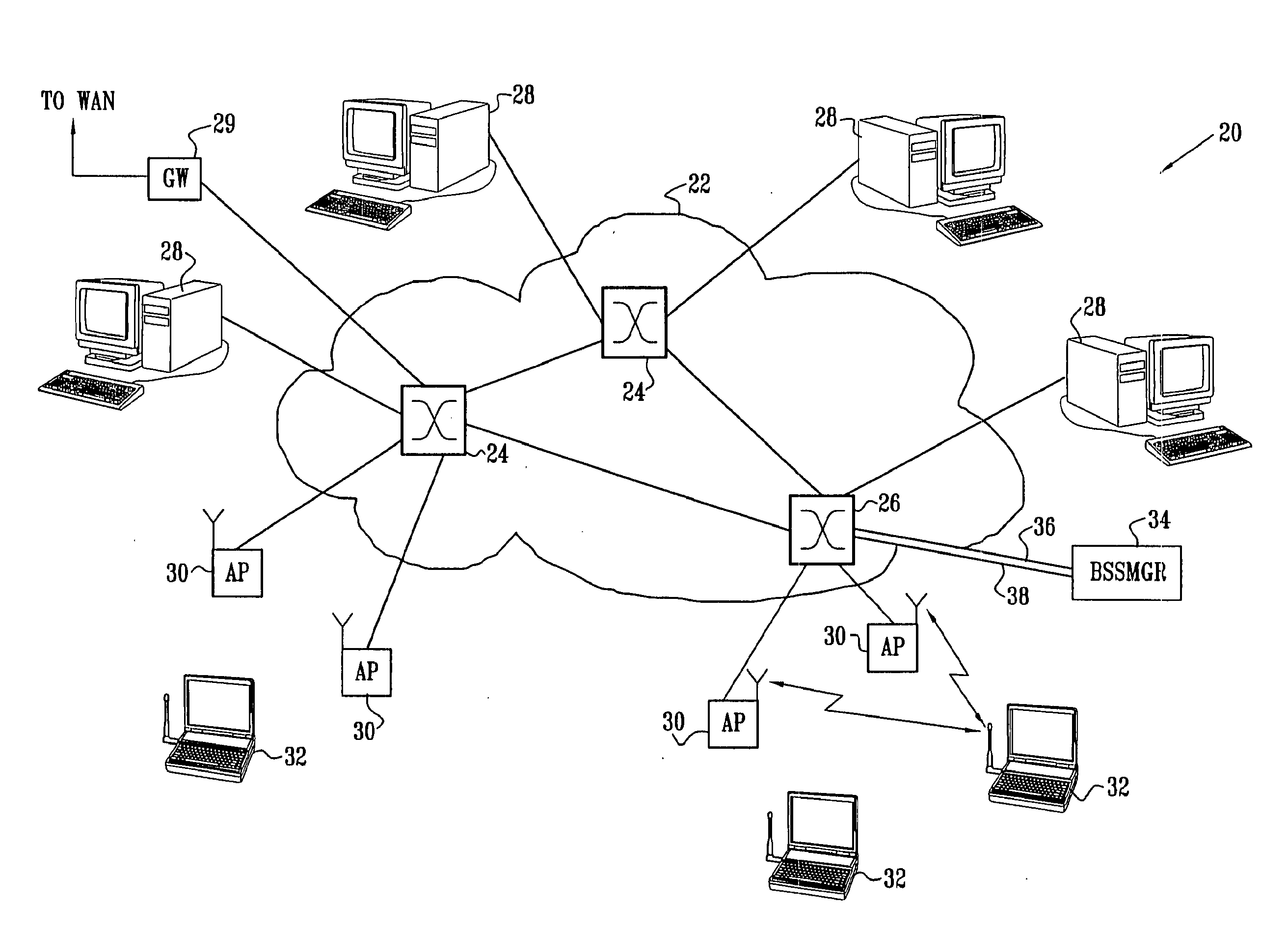
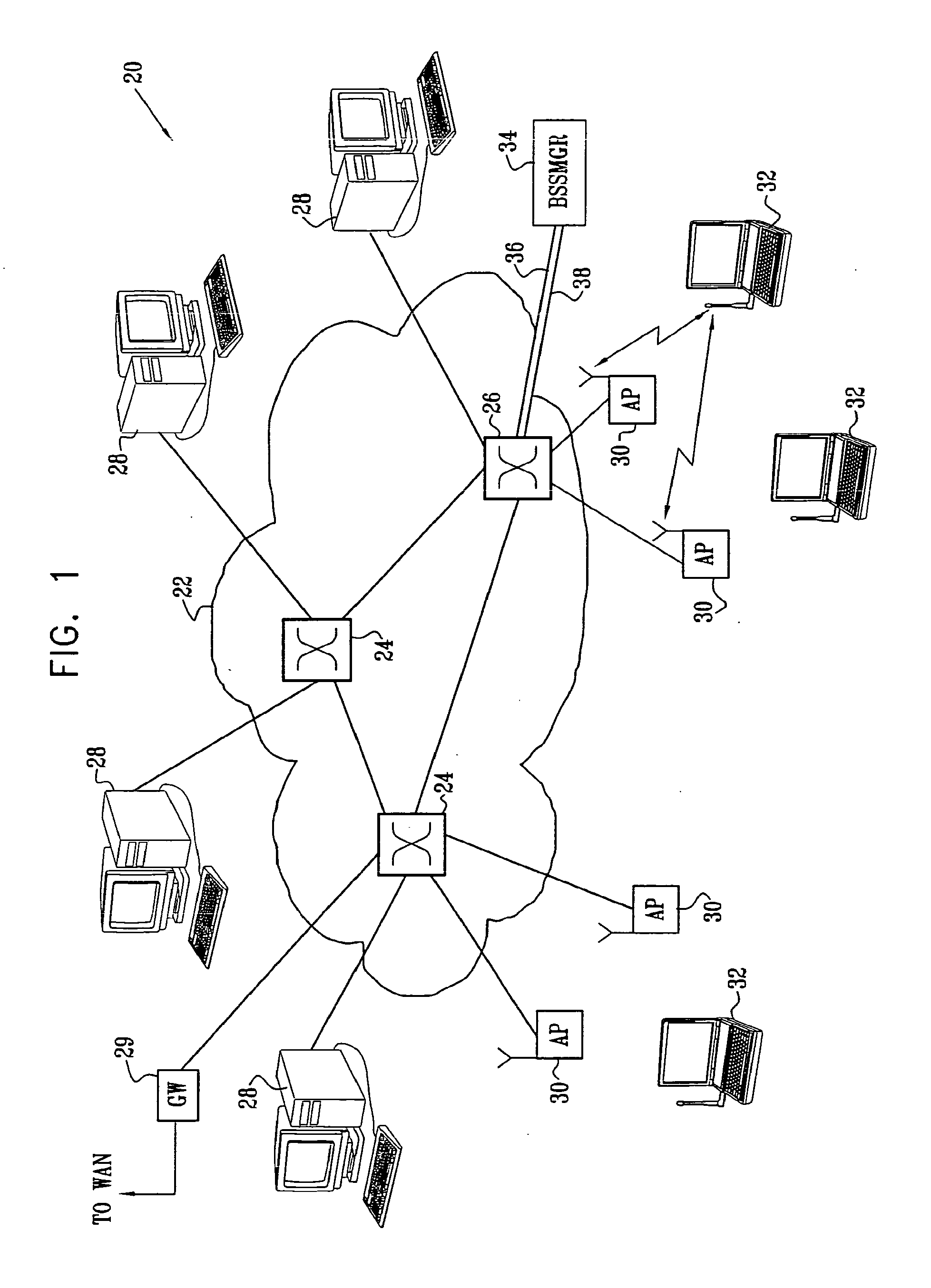
[0045]FIG. 1 is a block diagram that schematically illustrates a wireless LAN (WLAN) system 20, in accordance with an embodiment of the present invention. System 20 is built around a wired LAN 22, comprising LAN switches 24, 26. Although three switches are shown here by way of example, in practice LAN 22 may comprise a larger or smaller number of switches, in substantially any topology known in the art. Typically, LAN 22 comprises an Ethernet LAN, in accordance with one of the IEEE 802.3 standards. Preferably, for the purposes of the present embodiment, the LAN has a characteristic data rate of at least 1 Gbps, as provided, for instance, by Gigabit Ethernet LANs. Alternatively, system 20 may be built around a lower-speed LAN, such as a 100 Mbps Ethernet LAN. In either case, embodiments of the present invention provide novel methods for reducing latency of communication over LAN 22 between WLAN elements, as described below, in order to meet the tight timing requirements of the WLAN w...


PUM


Abstract

Apparatus for mobile communication includes a switch and a plurality of access points, which are arranged in a wireless local area network (WLAN) to communicate over the air on a common frequency channel with a mobile station using a common basic service set identification (BSSID) for all the access points. The access points are coupled by a LAN to the switch so that upon receiving at one or more of the access points an uplink signal transmitted over the WLAN by the mobile station on the common frequency channel, the one or more of the access points convey messages responsively to the uplink signal over the LAN to the switch. A manager node is coupled to the switch so as to receive the messages and is adapted to process the messages so as to select one of the access points to respond to the uplink signal.

Description

CROSS-REFERENCE TO RELATED APPLICATION[0001]This application is a continuation-in-part of U.S. patent application Ser. No. 10 / 664,631, filed Sep. 19, 2003, which is a continuation-in-part of U.S. patent application Ser. No. 10 / 214,271, filed Aug. 7, 2002. Both of these related applications are assigned to the assignee of the present patent application, and their disclosures are incorporated herein by reference.FIELD OF THE INVENTION[0002]The present invention relates generally to wireless communications, and specifically to methods and devices for improving the performance of wireless local area networks.BACKGROUND OF THE INVENTION[0003]Wireless local area networks (WLANs) are gaining in popularity, and new wireless applications are being developed. The original WLAN standards, such as “Bluetooth” and IEEE 802.11, were designed to enable communications at 1-2 Mbps in a band around 2.4 GHz. More recently, IEEE working groups have defined the 802.11a, 802.11b and 802.11g extensions to...

Claims


Application Information

Patent Timeline
Patent Type & Authority Applications(United States)
IPC IPC(8): H04W40/00H04B7/005H04L12/28H04L12/56H04W48/20H04W52/08H04W52/40H04W84/12H04W88/08
CPCH04J13/0048H04W48/20H04W52/08H04W52/40H04W84/12H04W88/08H04W92/045H04W92/20Y10S370/913
Inventor SHPAK, ERAN
Owner ALLIED TELESIS ISRAEL LTD
Why Eureka
Try Eureka