Communication between wireless access points over LAN cabling

a wireless access point and cabling technology, applied in the field of wireless communications, can solve the problems of slowing down the wlan access for all other users in its basic service set, unable to decipher either signal, and severely hampered the theoretical capability of new wlan technologies to offer enormous communication bandwidth to mobile users, etc., to achieve the effect of enhancing the coverage and speed of wlan systems

Active Publication Date: 2007-02-13
ALLIED TELESIS ISRAEL LTD
View PDF20 Cites 24 Cited by
  • Summary
  • Abstract
  • Description
  • Claims
  • Application Information

AI Technical Summary

Benefits of technology

[0007]It is an object of some aspects of the present invention to provide

Problems solved by technology

The theoretical capability of new WLAN technologies to offer enormous communication bandwidth to mobile users is severely hampered by the practical limitations of wireless communications.
Therefore, even when wireless access points are carefully positioned throughout a building, some “black holes” generally remain—areas with little or no radio reception.
A single mobile station with poor reception due to distance or radio propagation problems can slow down WLAN access for all other users in its basic service set (BSS—the group of mobile stations communicating with the same access point).
If a rec

Method used


Image

  • Communication between wireless access points over LAN cabling
  • Communication between wireless access points over LAN cabling
  • Communication between wireless access points over LAN cabling

Examples


Embodiment Construction

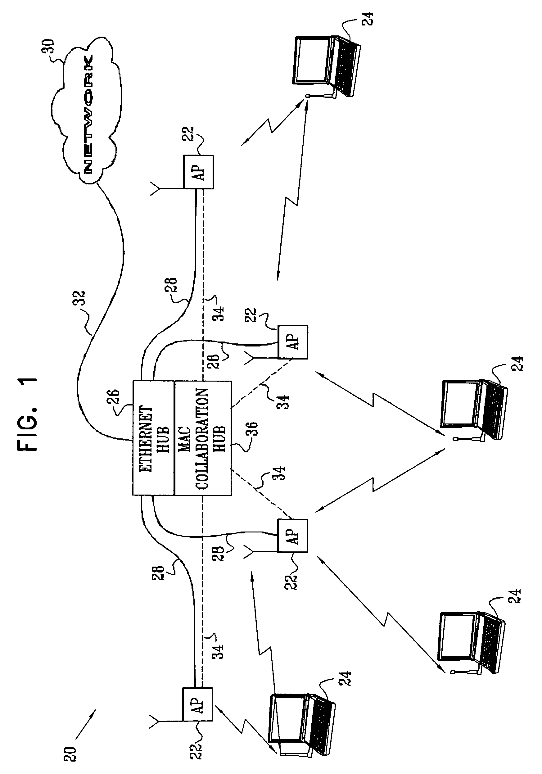
[0031]FIG. 1 is a block diagram that schematically illustrates a wireless LAN (WLAN) system 20, in accordance with a preferred embodiment of the present invention. System 20 comprises multiple access points 22, which are configured for data communication with mobile stations 24. The mobile stations typically comprise computing devices, such as desktop, portable or handheld devices, as shown in the figure. In the exemplary embodiments described hereinbelow, it is assumed that the access points and mobile stations communicate with one another in accordance with one of the standards in the IEEE 802.11 family and observe the 802.11 medium access control (MAC) layer conventions. Details of the 802.11 MAC layer are described in ANSI / IEEE Standard 801.11 (1999 Edition), and specifically in Part 11: Wireless LAN Medium Access Control (MAC) and Physical Layer (PHY) Specifications, which is incorporated herein by reference. The principles of the present invention, however, are not limited to ...


PUM


Abstract

Apparatus for network communication includes a cable arranged to form a wired local area network (LAN), the cable comprising at least first and second conductors. A plurality of access points are interconnected by the cable and are arranged in a wireless local area network (WLAN) to communicate over the air on a common frequency channel with a mobile station. The access points are adapted to convey data to and from the mobile station over the LAN via the first conductor and to exchange control messages among the access points via the second conductor.

Description

CROSS-REFERENCE TO RELATED APPLICATIONS[0001]This application claims the benefit of U.S. Provisional Patent Applications 60 / 377,645, 60 / 377,646, 60 / 377,647 and 60 / 377,650, all of which were filed May 6, 2002. This application is a continuation-in-part of a U.S. patent application Ser. No. 10 / 214,271 entitled “Collaboration Between Wireless LAN Access Points,” filed Aug. 7, 2002. All these, related applications are incorporated herein by reference.FIELD OF THE INVENTION[0002]The present invention relates generally to wireless communications, and specifically to methods and devices for improving the performance of wireless local area networks.BACKGROUND OF THE INVENTION[0003]Wireless local area networks (WLANs) are gaining in popularity, and new wireless applications are being developed. The original WLAN standards, such as “Bluetooth” and IEEE 802.11, were designed to enable communications at 1–2 Mbps in a band around 2.4 GHz. More recently, IEEE working groups have defined the 802.1...

Claims


Application Information

Patent Timeline
IPC IPC(8): H04J1/00H04B7/005H04L12/28H04L12/56H04W52/08H04W52/40H04W84/12H04W88/08H04W92/20
CPCH04J13/0048H04W52/08H04W92/20H04W84/12H04W88/08H04W52/40
Inventor SHPAK, ERAN
Owner ALLIED TELESIS ISRAEL LTD
Why Eureka
Try Eureka