Development magnet roller, development device, process cartridge and image forming apparatus

a development magnet roller and development device technology, applied in the field of electrophotography image forming apparatus, can solve the problems of adverse effects on the transfer device, adverse effects on the fixing device, and the reliability of the image forming apparatus is a factor decreasing the reliability of the image forming apparatus, so as to reduce the omission of trailing edges, suppress carrier adhesion, and improve the effect of surface magnetic for

Active Publication Date: 2005-03-24
RICOH KK
View PDF19 Cites 3 Cited by
  • Summary
  • Abstract
  • Description
  • Claims
  • Application Information

AI Technical Summary

Benefits of technology

[0014] According to a preferred embodiment of the present invention, a development magnet roller for use in a development roller of an electrophotographic image forming apparatus is provided. The development magnet roller has a development pole to form a magnetic field causing a developer born on a surface of the development roller including the development magnet roller to rise in a form of a series of ears in a development area of the image forming apparatus where the development roller opposes an image bearing member, and in a magnetic flux density distribution in a normal line direction of the development pole, a peak magnetic flux density is 120 mT or greater, a zero gauss region width is 70° or greater, and a half-value region width is 40° or smaller. Thereby, while obtaining a relatively large surface magnetic force of the development roller necessary for development, by making a zero gauss region width in the magnetic flux density distribution in the normal line direction of the development pole relatively large, carrier adhesion can be suppressed, and at the same time, by narrowing a half-value region width in the magnetic flux density distribution, trailing edge omission can be improved.
[0015] In the above-described development magnet roller, the magnetic flux density distribution in the normal line direction of the development pole may be formed such that a half-value region center angle is shifted 3° or more toward a downstream side of a zero gauss region center angle in a direction in which the developer born on the surface of the development roller is conveyed. Thereby, a magnetic force between the development pole and a downstream side pole is prevented from rapidly plunging, so that carrier adhesion can be further suppressed.
[0016] The above-described development magnet roller may be configured such that a magnet block is buried in the development magnet roller at a part thereof corresponding to the development pole. Thereby, adjusting the half-value region center angle relative to the zero gauss region center angle in the magnetic flux density distribution in the normal line direction of the development pole is facilitated.
[0017] In the development magnet roller described immediately above, a zero gauss regi

Problems solved by technology

This causes adverse effects to the transfer device.
This causes adverse effects to the fixing device.
Thus, carrier adhesion is a factor decreasing reliability of an image forming apparatus.
To avoid carrier adhesion, it is conceivable to decrease the electric force applied to the carriers from the latent image

Method used


Image

  • Development magnet roller, development device, process cartridge and image forming apparatus
  • Development magnet roller, development device, process cartridge and image forming apparatus
  • Development magnet roller, development device, process cartridge and image forming apparatus

Examples


Embodiment Construction

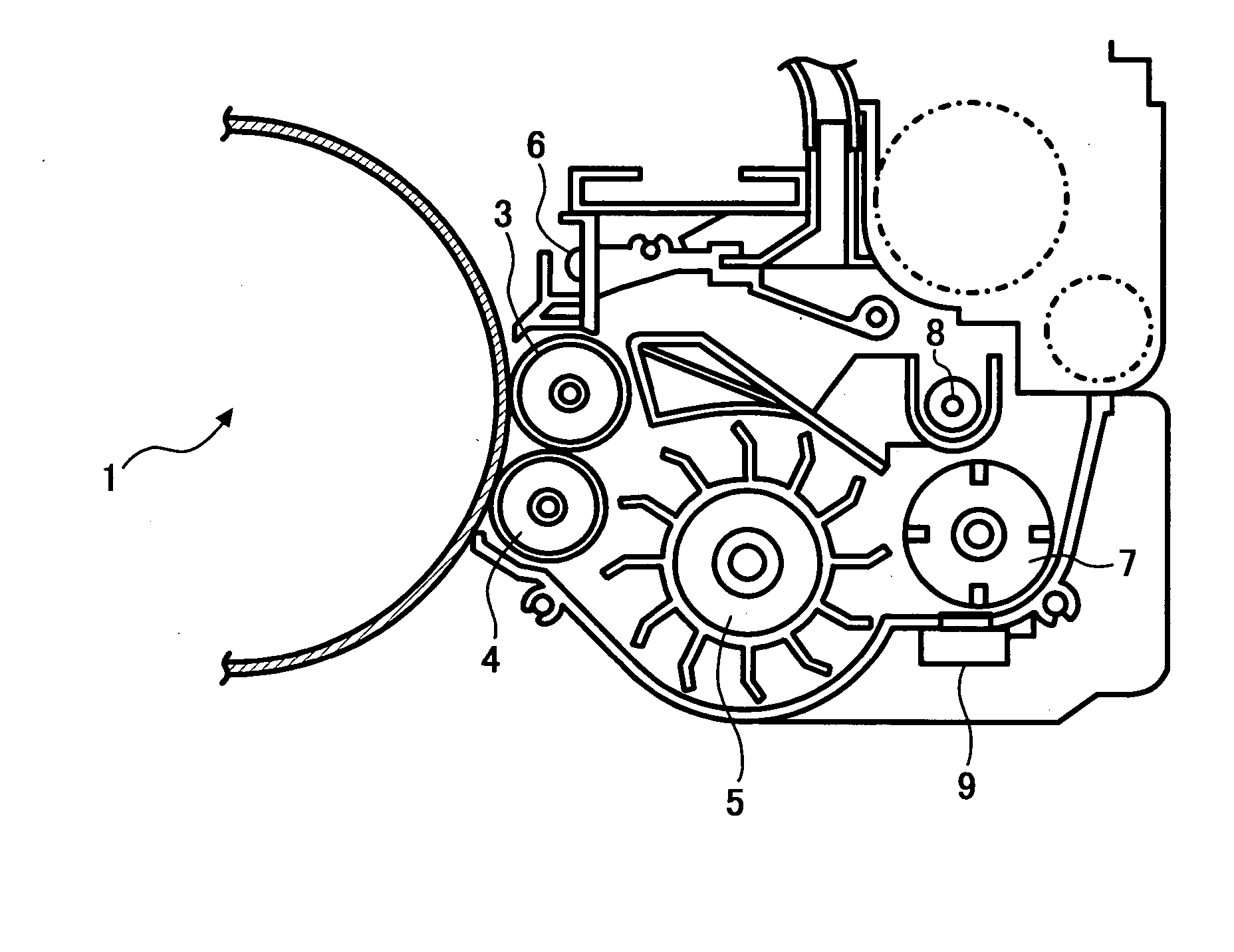
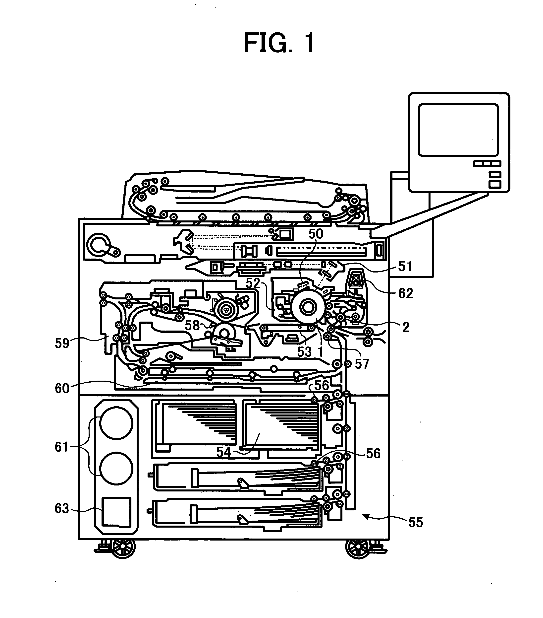
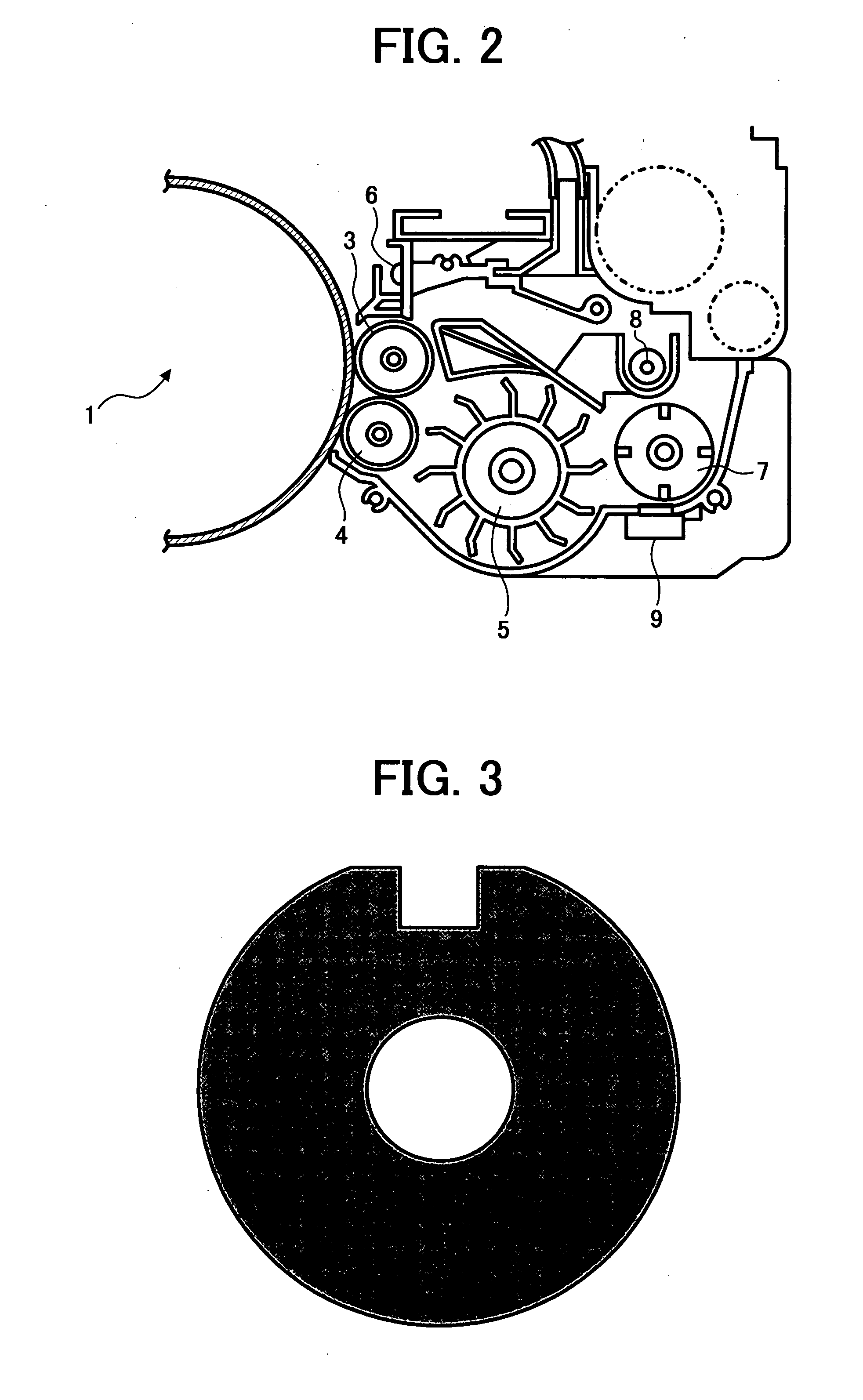
[0024] Referring now to the drawings, wherein like reference numerals designate identical or corresponding parts throughout the several views, preferred embodiment of the present invention are described.

[0025] In a two-component development device, the magnetic waveform of a development pole of a development roller has been examined to improve carrier adhesion and trailing edge omission phenomena. First, the peak magnetic flux density (maximum magnetic force in a magnetic force distribution curve in the normal line direction) of the development pole has been examined, and it has been found that higher the peak magnetic flux density is, it is more advantageous for improving carrier adhesion. It is believed that as the peak magnetic flux density of a development pole is higher, the magnetic force in a development area is higher, so that carrier adhesion is hard to occur.

[0026] Next, the zero gauss region width (angle width at parts of a magnetic force distribution curve in the norma...


PUM


Abstract

A development magnet roller for use in a development roller of an electrophotographic image forming apparatus is provided. The development magnet roller has a development pole to form a magnetic field causing a developer born on a surface of the development roller including the development magnet roller to rise in a form of a series of ears in a development area of the image forming apparatus where the development roller opposes an image bearing member, and in a magnetic flux density distribution in a normal line direction of the development pole, a peak magnetic flux density is 120 mT or greater, a zero gauss region width is 70° or greater, and a half-value region width is 40° or smaller.

Description

CROSS-REFERENCE TO RELATED APPLICATIONS [0001] The present application claims priority and contains subject matter related to Japanese Patent Application No. 2003-286485 filed in the Japanese Patent Office on Aug. 5, 2003, and the entire contents of which are hereby incorporated herein by reference. BACKGROUND OF THE INVENTION [0002] 1. Field of the Invention [0003] The present invention relates to an image forming apparatus of electrophotography such as copiers, facsimile apparatuses and printers, and more particularly relates to a two-component development device in which a two-component developer born on the surface of a development roller is caused to rise in a form of a series of ears to contact a latent image bearing member and thereby a latent image on the latent image bearing member is visualized with toner of the developer. [0004] 2. Discussion of the Background [0005] Two-component development devices using a two-component developer in which magnetic particles called carri...

Claims


Application Information

Patent Timeline
IPC IPC(8): H01F7/02G03G15/09
CPCG03G2215/0634G03G15/0921
Inventor KAMIYA, NORIYUKIYASUNAGA, TAKAHIROIMAMURA, TSUYOSHIKAMOI, SUMIOKOETSUKA, KYOHTAKAKEGAWA, MIEKO
Owner RICOH KK
Why Eureka
Try Eureka