Multi-piece oil ring

a multi-piece, oil ring technology, applied in the direction of brake systems, machines/engines, transportation and packaging, etc., can solve the problems of affecting the function of engine components such as oil rings, clogging of passages for lubricating oil, wear of components, etc., to achieve effective suppression of adhesion and deposition of oil sludge, prevent the occurrence of sticking of multi-piece oil ring, and large surface area

Active Publication Date: 2014-01-23
RIKEN CO LTD
View PDF9 Cites 10 Cited by
  • Summary
  • Abstract
  • Description
  • Claims
  • Application Information

AI Technical Summary

Benefits of technology

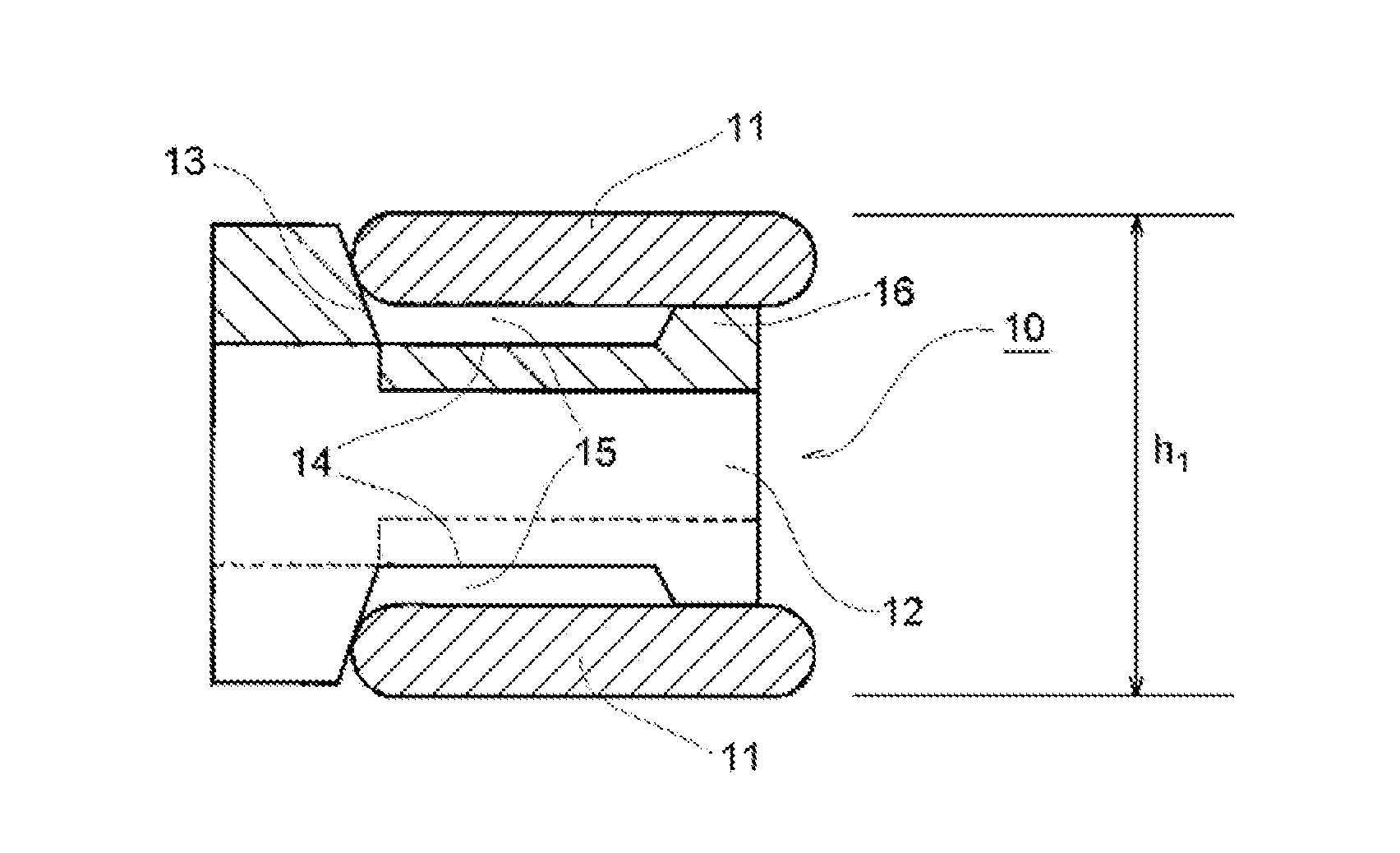
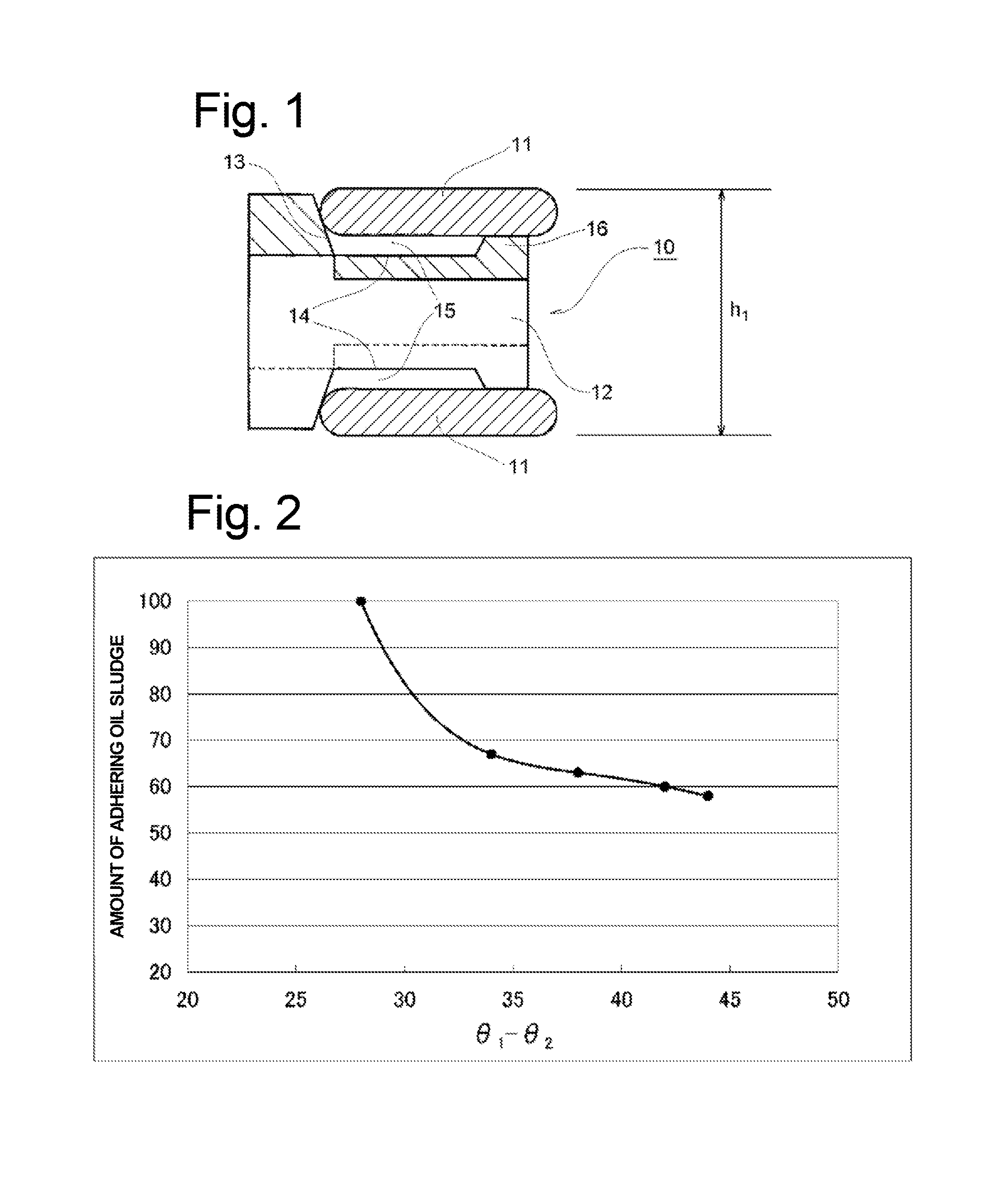
[0016]In the multi-piece oil ring of the invention, the oil repellency of the side faces of the side rails that face the spacer expander is higher than the oil repellency of the surface of the spacer expander, so that a prescribed difference is provided therebetween. Since the flow of the oil from the side rails toward the spacer expander is accelerated by convection caused by the difference in oil repellency and the difference in temperature, the generated oil sludge can be rapidly discharged. Therefore, adhesion and deposition of oil sludge can be effectively suppressed, and the occurrence of sticking of the multi-piece oil ring can be prevented.
[0017]In the present invention, by coating the spacer expander having a large surface area with a metal coating having high heat dissipation, the heat dissipation effect from the multi-piece oil ring to the oil can be improved. Accordingly, an increase in temperature of the multi-piece oil ring is suppressed. Therefore, even when the side rails are coated with a fluorine-containing coating, thermal decomposition and degradation of the coating are suppressed, and a high effect of preventing adhesion and deposition of oil sludge is maintained even after long-term operation.

Problems solved by technology

These unburned products and denatured products of oil additives are generally collectively referred to as “oil sludge.” If such oil sludge adheres to engine components and is then deposited thereon, these components may be worn, and passages for the lubricating oil may be clogged, so that the functions of the engine components such as oil rings may be hindered.
In particular, when the three-piece oil ring has a reduced axial width, the deposition of oil sludge may cause sticking of the side rails 11 to the spacer expander 12.
When sticking occurs, the conformability of the side rails 11 to the inner peripheral face of the cylinder is lowered, and the oil consumption is likely to increase.
However, with the conventional coating structures, the effect of preventing adhesion and deposition of oil sludge is not sufficient.

Method used


Image

  • Multi-piece oil ring
  • Multi-piece oil ring

Examples


example 1

(1) Production of Side Rails

[0059]A closed container was charged with respective monomers, a polymerization solvent, and a polymerization initiator in a mass ratio shown in TABLE 2, and the reaction was allowed to proceed at 70° C. for 26 hours to thereby obtain a polymerized composition. The polymerization initiator used was an initiator V-601 manufactured by Wako Pure Chemical Industries, Ltd., and the solvent used was metaxylene hexafluoride (m-XHF). The obtained polymerized composition was diluted with m-XHF such that the content of the polymer was 5% by mass to thereby obtain a coating solution. Side rails formed of 17Cr martensitic stainless steel were immersed in the coating solution for 30 seconds. After the side rails were removed from the solution, they were placed in an electric furnace and subjected to heat treatment in air at 120° C. for 1 hour. The angle of contact (θ1) of the paraffin-based lubricating oil with the side face portions of the obtained side rails at 150°...

example 2

(1) Production of Side Rails

[0064]Side rails were produced as in Example 1.

(2) Production of Spacer Expander

[0065]The surface of a rolled strip (made of SUS304) for a spacer expander that had an R-shaped edge was polished such that the line surface roughness Ra (center line average roughness) was 0.02 μm±0.01 μm and then degreased in acetone. While wound at a rate of 3 m / min, this rolled strip was subjected to Cu plating treatment using a wire plating apparatus in a plating bath containing 220 g / L of copper sulfate, 60 g / L of sulfuric acid, and 50 mg / L of chlorine ions. The thickness of the obtained Cu plating film was about 5 μm. After the plating treatment, the wire was placed in an electric furnace and subjected to heat treatment at 500° C. for 60 minutes.

[0066]Then the wire was gear-molded into an axially wavy shape. Then tabs were formed at one end portion of the wire by axial shearing and then molded and cut into a ring shape such that the tabs were on the inner peripheral sid...

example 3

(1) Production of Side Rails

[0068]A closed container was charged with respective monomers, a polymerization solvent, and a polymerization initiator in a mass ratio shown in TABLE 2, and the reaction was allowed to proceed at 70° C. for 26 hours to thereby obtain a polymerized composition. The polymerization initiator used was an initiator V-601 manufactured by Wako Pure Chemical Industries, Ltd., and the solvent used was metaxylene hexafluoride (m-XHF). The obtained polymerized composition was diluted with m-XHF such that the content of the polymer was 5% by mass to thereby obtain a coating solution. Side rails formed of 17Cr martensitic stainless steel were immersed in the coating solution for 30 seconds. After the side rails were removed from the solution, they were placed in an electric furnace and subjected to heat treatment in air at 120° C. for 1 hour. The angle of contact (θ1) of the paraffin-based lubricating oil with the side face portions of the obtained side rails at 150°...


PUM


Abstract

A multi-piece oil ring is provided in which, even after long-term operation of an engine, adhesion and deposition of oil sludge are prevented, sticking of components does not occur, and a high oil control function can be maintained. The multi-piece oil ring includes a spacer expander and a pair of upper and lower side rails supported by the spacer expander. To achieve the above features, at least side faces of the side rails that face the spacer expander are coated with a fluorine-containing coating, and the spacer expander is coated with a metal coating. The angle of contact (θ1) of a paraffin-based lubricating oil with the portions of the side rails at 150° C. that are coated with the fluorine-containing coating is 50° or larger, and the angle of contact (θ2) of the paraffin-based lubricating oil with the portion of the spacer expander at 150° C. that is coated with the metal coating is 10 to 50°. The difference between θ1 and θ2 (θ1-θ2) is 30° or larger.

Description

TECHNICAL FIELD[0001]The present invention relates to a multi-piece oil ring to be attached to a piston of an internal combustion engine and more particularly to a multi-piece oil ring for an internal combustion engine that can effectively prevent adhesion and deposition of oil sludge generated by deterioration of lubricating oil for the engine and also sticking of components caused by the adhesion and deposition of oil sludge.BACKGROUND ART[0002]In an internal combustion engine, lubricating oil is heated and exposed to blowby gas during long-term operation of the engine, and unburned products of hydrocarbons and denatured products of oil additives are contained in the lubricating oil at the same time. These unburned products and denatured products of oil additives are generally collectively referred to as “oil sludge.” If such oil sludge adheres to engine components and is then deposited thereon, these components may be worn, and passages for the lubricating oil may be clogged, so ...

Claims


Application Information

Patent Timeline
Patent Type & Authority Applications(United States)
IPC IPC(8): F16J9/12F16J9/26
CPCF16J9/12F16J9/26F16J9/066F16J9/064F16J9/203
Inventor TAKAHASHI, JUNICHIONO, TAKASHIMURAMATSU, GYOICHIKAWA, TAKAYUKI
Owner RIKEN CO LTD
Why Eureka
Try Eureka