Thermal-transfer printer

a technology of thermal transfer printer and platen roller, which is applied in the direction of printing, printing mechanism, power drive mechanism, etc., can solve the problems of non-uniform printing, rattling of the platen roller in the direction of conveying the sheet, and bringing about non-uniform printing, so as to prevent non-uniform printing. , the effect of preventing non-uniform printing

Inactive Publication Date: 2005-03-24
FUNAI ELECTRIC CO LTD
View PDF2 Cites 6 Cited by
  • Summary
  • Abstract
  • Description
  • Claims
  • Application Information

AI Technical Summary

Benefits of technology

[0023] The invention has been conveyed out in order to resolve the above-described problem and it is an object of the invention to provide a thermal-transfer printer capable of restraining nonuiformity in printing from being brought about owing to the fact that a printing position of a thermal head relative to a sheet is shifted in a direction of conveying the sheet.

Problems solved by technology

However, owing to a dimensional error, as shown in FIG. 14, there is brought about a drawback that there is frequently a case of producing a clearance 124 between the bearing member 123 and the supporting shaft 109.
As a result, there occurs a problem that nonuniformity in printing is brought about.
Further, according to the thermal-transfer printer disclosed in JP-A-2-160558, mentioned above, a structure for restraining rattling of the platen roller for pressing a sheet to the thermal head is not disclosed and therefore, there is brought about a drawback of causing rattling in the platen roller in the direction of conveying the sheet.
Thereby, also in the thermal-transfer printer disclosed in JP-A-2-160558, mentioned above, similar to the thermal-transfer printer owing to the embodiment of the prior art shown in FIG. 9, there occurs a problem that nonuniformity in printing is brought about owing to the fact that a printing position of the thermal head relative to the sheet is shifted in the direction of conveying the sheet.
Therefore, also in the thermal-transfer printers disclosed in JP-A-3-049961 and JP-A-9-071022, mentioned above, similar to the thermal-transfer printer according to the example of the prior art shown in FIG. 9, there poses the problem that nonuniformity in printing is brought about owing to the fact that the printing position of the thermal head relative to the sheet is shifted in the direction of conveying the sheet.

Method used


Image

  • Thermal-transfer printer
  • Thermal-transfer printer
  • Thermal-transfer printer

Examples


Embodiment Construction

[0042] Referring now to the accompanying drawings, a description will be given in detail of preferred embodiments of the invention.

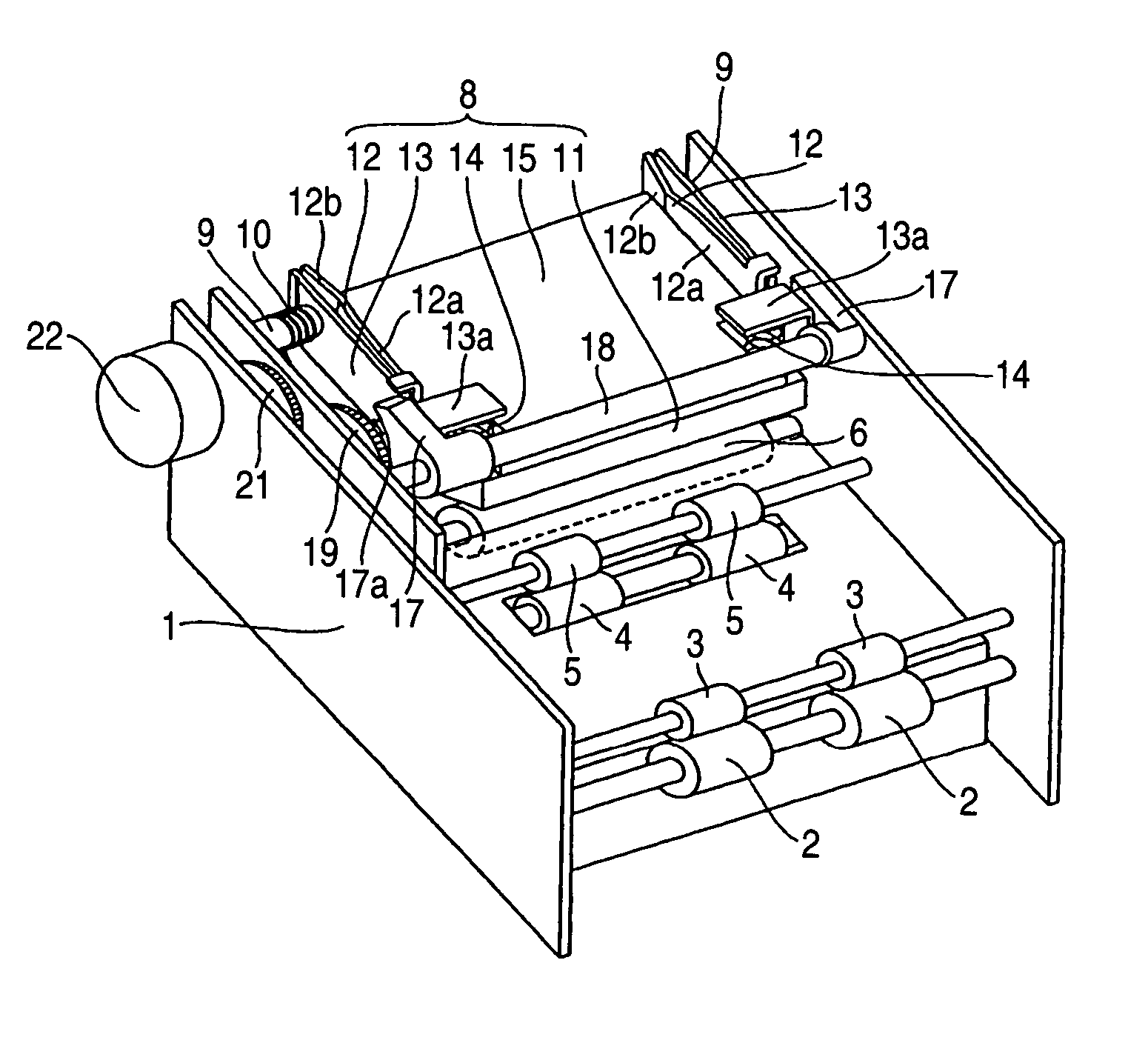
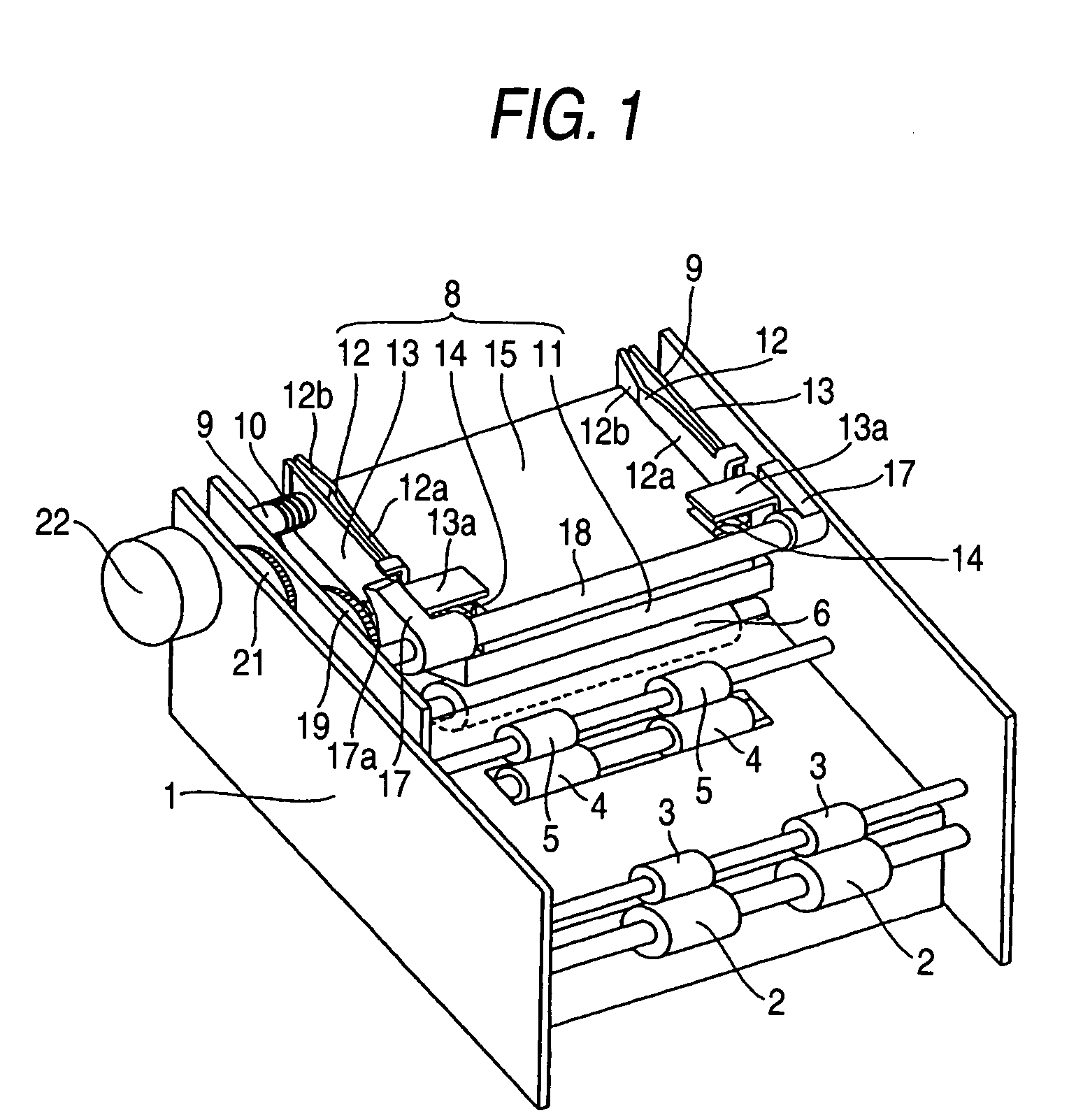
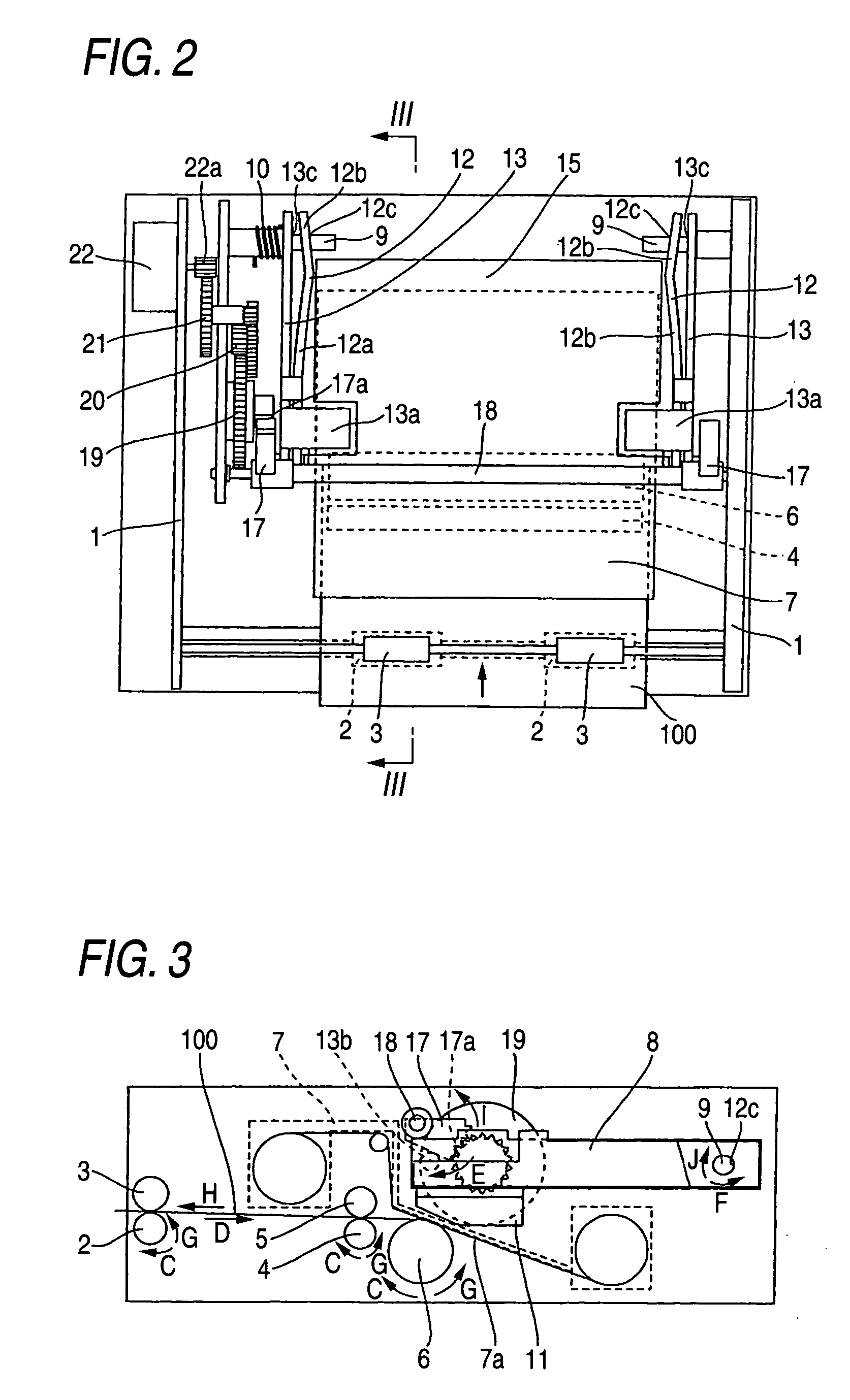
[0043]FIG. 1 is a perspective view showing an overall structure of a thermal-transfer printer according to a first embodiment of the invention. Further, FIG. 1 shows a state of removing an ink cartridge of the thermal-transfer printer. FIG. 2 is a top view of the thermal-transfer printer according to the first embodiment shown in FIG. 1. FIG. 3 and FIG. 4 are sectional views taken along III-III line shown in FIG. 2. FIG. 5 is a disassembled perspective view showing a structure of a heating portion of the thermal-transfer printer according to the first embodiment shown in FIG. 1. FIG. 6 is a side view of the heating portion of the thermal-transfer printer according to the first embodiment shown in FIG. 1. Further, FIG. 6 shows a state of removing a head supporting arm and a compression coil spring of the heating portion. FIG. 7 and FIG. 8 are enlarged se...


PUM


Abstract

The thermal-transfer printer includes: a pair of head attaching arms 12 having fitting holes 12c respectively inserted with support shafts 9 and having center lines inclined to axis lines of the supporting shafts 9 by a predetermined inclination angle; and supporting shaft attaching portions 12b being bent by bending lines 12d that intersects with a line connecting the fitting holes 12c and a printing position of a thermal head 11 relative to a sheet 100. The fitting hole 12c of respective supporting shaft attaching portion 12b are attached to the supporting shafts 9 in a state of being elastically bent in directions opposed to each other such that predetermined inclination angles of the supporting shafts 9 of center lines of the fitting hole 12c of the supporting shaft attaching portion 12b relative to axis lines of the supporting shafts 9 are reduced.

Description

BACKGROUND OF THE INVENTION [0001] 1. Field of the Invention [0002] The present invention relates to a thermal-transfer printer, particularly relates to a thermal-transfer printer having a thermal head for thermally transferring ink onto a sheet. [0003] 2. Description of the Related Art [0004] Conventionally, there is known a thermal-transfer printer having a thermal head for thermally transferring ink onto a sheet. [0005] In JP-A-2-160558, there is disclosed a thermal-transfer printer for pressing a platen roller to a thermal head by pivoting a positioning member for supporting the platen roller centering on a predetermined axis. [0006] In JP-A-3-049961, there is disclosed a thermal-transfer printer for restraining a thermal head from producing a positional shift in a longitudinal direction by providing an attaching plate with a compression spring for restraining the attaching plate attached with the thermal head from moving in a longitudinal direction of the thermal head. [0007] I...

Claims


Application Information

Patent Timeline
Patent Type & Authority Applications(United States)
IPC IPC(8): B41J2/32B41J2/325B41J25/312
CPCB41J25/312B41J2/325
Inventor SAWAI, KUNIO
Owner FUNAI ELECTRIC CO LTD
Why Eureka
Try Eureka