Terminal for electrical connector

a technology for terminals and electrical connectors, applied in the direction of final product manufacturing, coupling device connections, sustainable manufacturing/processing, etc., can solve the problem of holding soldering tins, etc., and achieve the effect of good soldering

Inactive Publication Date: 2005-03-24
HON HAI PRECISION IND CO LTD
View PDF5 Cites 21 Cited by
  • Summary
  • Abstract
  • Description
  • Claims
  • Application Information

AI Technical Summary

Benefits of technology

[0008] An object of the present invention is to provide a terminal for an electrical connector having a tail portion which has good soldering effect and can be connected to a PCB reliably.

Problems solved by technology

However, a rectangular bottom face of the soldering portion 54 has poor effect of holding soldering tin and the connecting area between the soldering portion and the connecting portion has a smooth, continuous surface.

Method used


Image

  • Terminal for electrical connector
  • Terminal for electrical connector
  • Terminal for electrical connector

Examples


Embodiment Construction

[0015] Reference will now be made in detail to the preferred embodiment of the present invention.

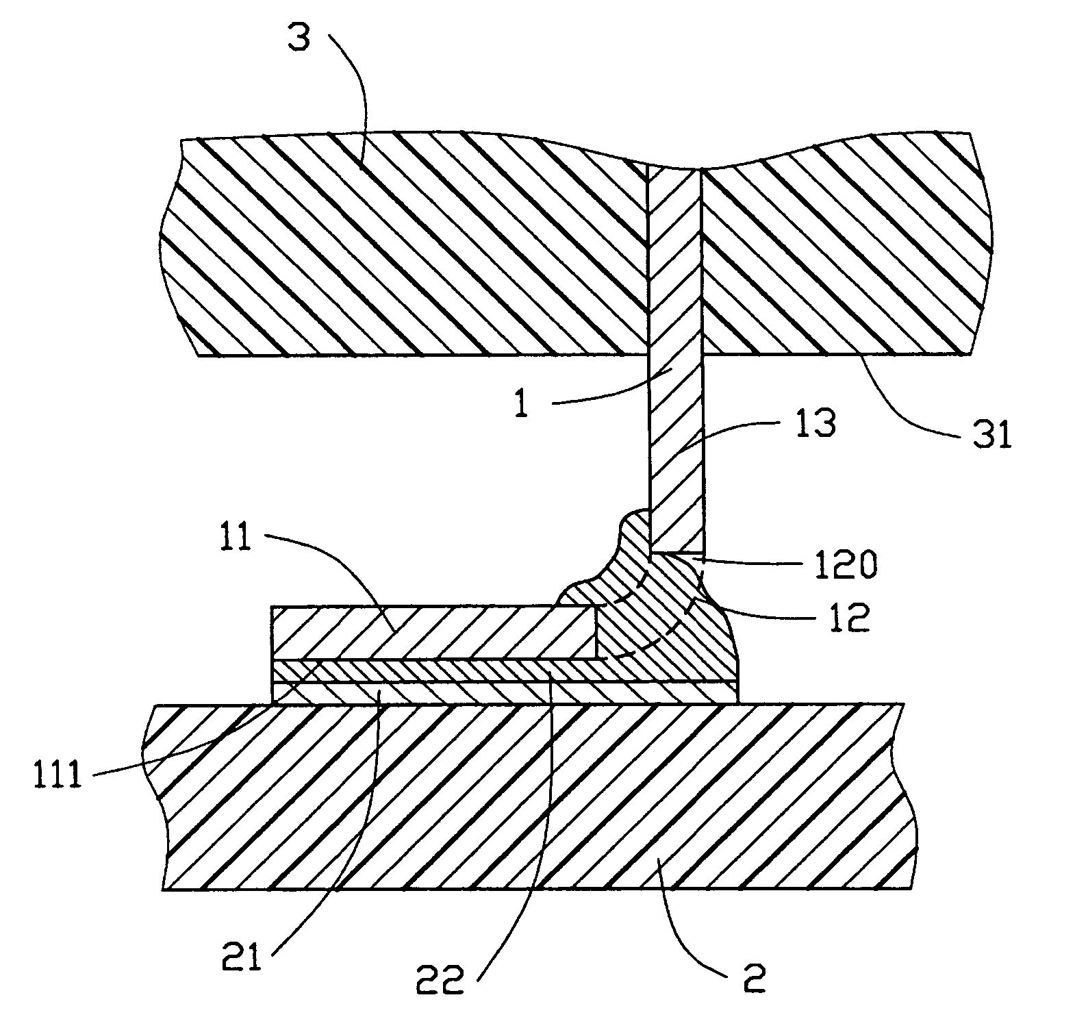
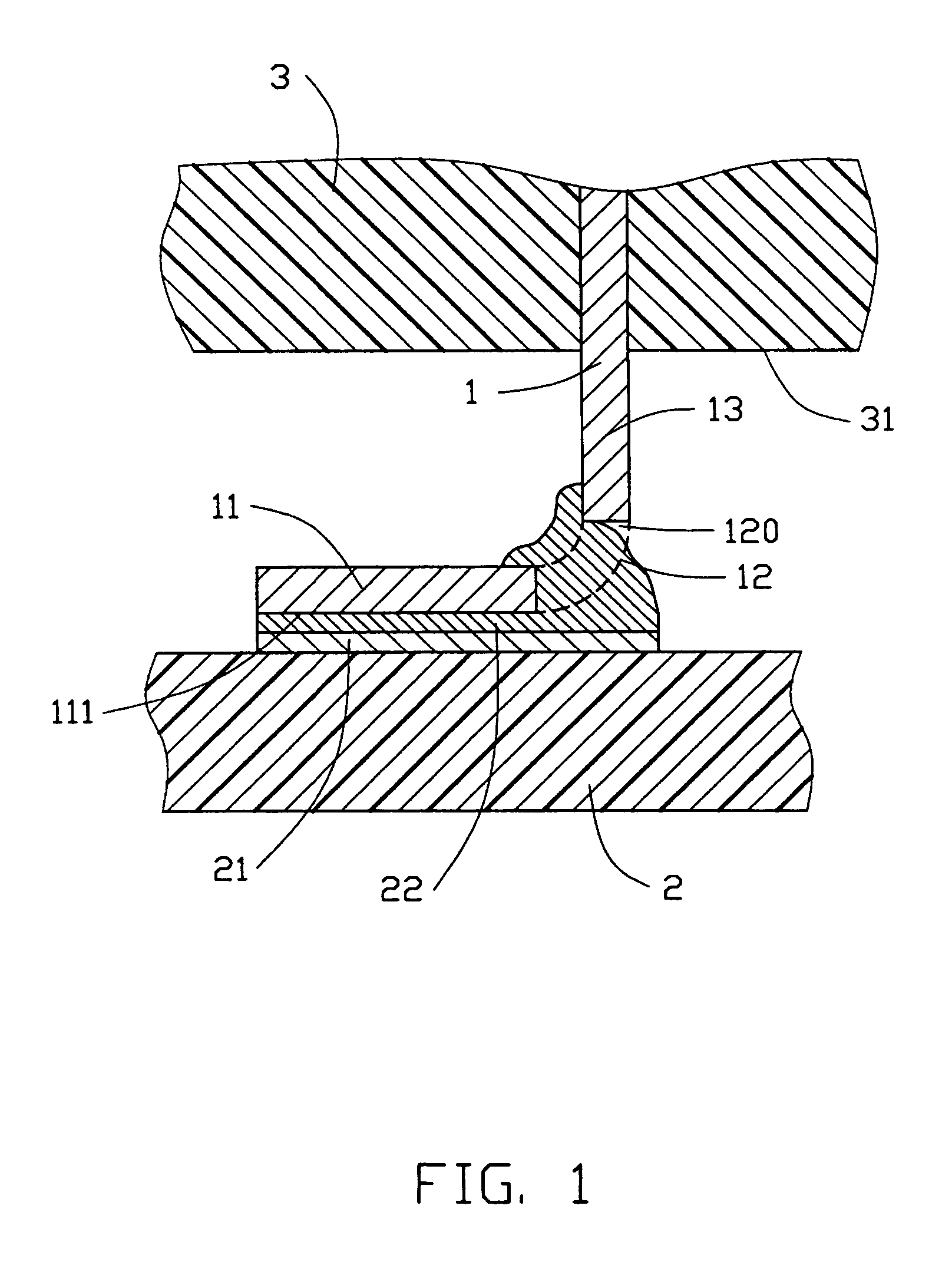
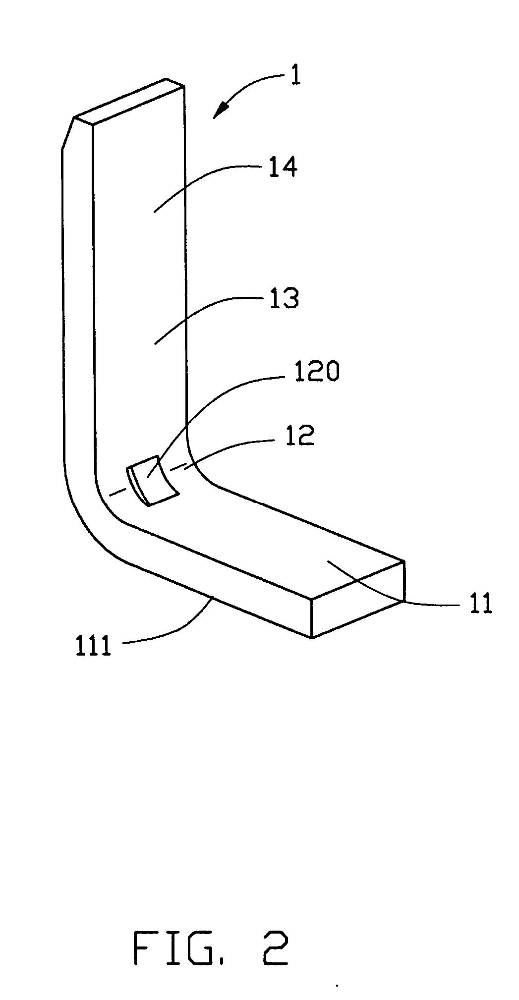
[0016] Referring to FIGS. 1-2, a terminal 1 in accordance with the present invention comprises a flat soldering portion 11, a flexed portion 12 connecting with an end of the soldering portion 11, a connecting portion 13 extending upwardly from the flexed portion 12 and a contacting portion 14 further extending upwardly from the connecting portion 13 for mating with a complementary connector (not shown). The soldering portion 11 has a soldering face 111 and the connecting portion 13 extends away from the soldering face 111. A rectangular overflowing aperture 120 is defined through a center of the flexed portion 12.

[0017] The contacting portion 14 of the terminal 1 is received in an insulative housing 3 of an electrical connector. The connecting portion 13 extends downwardly out of a bottom face 31 of the insulative housing 3. The flexed portion 12 is formed with an arc, with a smooth su...


PUM


Abstract

A terminal (1) for an electrical connector includes a flat soldering portion (11), a flexed portion (12) extending from the soldering portion, and a contacting portion (14) extending upwardly from the flexed portion. The soldering portion has a soldering face (111) and the connecting portion extends away from the soldering face. A rectangular overflowing aperture (120) extends through a centre of the flexed portion. Thus, the terminal is securely soldered on a printed circuit board to thereby achieve a reliable electrical connection between the terminal and the printed circuit board.

Description

BACKGROUND OF THE INVENTION [0001] 1. Field of the Invention [0002] The present invention generally relates to a terminal for an electrical connector, and more particularly to a terminal having good soldering quality. [0003] 2. Description of Related Art [0004] In the electronic industry, an electrical connector is usually mounted on a printed circuit board (PCB) with a tail portion of the terminal connecting with a corresponding trace of the PCB. Generally, the tail portion of the terminal can be inserted into a corresponding through hole of the PCB for building an electrical connection between the electrical connector and the PCB, the method of which is referred as “Through Hole Technology” (THT). Also, the tail portion can extend parallel to the PCB and be soldered on an electrical pad disposed on a surface of the PCB, the method of which is referred as “Surface Mount Technology” (SMT). [0005] The trend to reduce the size of the electronic equipment, has resulted in an ongoing dr...

Claims


Application Information

Patent Timeline
Patent Type & Authority Applications(United States)
IPC IPC(8): H01R4/02H01R12/00H01R12/55H01R13/405H01R43/16H05K3/34
CPCH01R4/028H01R12/57H05K2201/1084H05K2201/10189H05K3/3426Y02P70/50
Inventor ZHANG, CHI
Owner HON HAI PRECISION IND CO LTD
Why Eureka
Try Eureka