A high-efficiency LED lamp chip soldering equipment based on digital linear dimming technology

A LED lamp, digital linear technology, applied in welding equipment, metal processing equipment, tin feeding device, etc., can solve problems affecting welding efficiency, tin outflow difficulties, etc., achieve good soldering effect, simple structure, full and firm solder joints Effect

Active Publication Date: 2022-07-22
浙江凯友照明科技有限公司
View PDF10 Cites 0 Cited by
  • Summary
  • Abstract
  • Description
  • Claims
  • Application Information

AI Technical Summary

Problems solved by technology

[0004] However, when the equipment is in use, changing the shape of the arc-shaped metal cover will not change the overall volume of the tin storage chamber, which will make it difficult for molten tin to flow out of the tin outlet hole, thereby affecting welding efficiency

Method used


Image

  • A high-efficiency LED lamp chip soldering equipment based on digital linear dimming technology
  • A high-efficiency LED lamp chip soldering equipment based on digital linear dimming technology
  • A high-efficiency LED lamp chip soldering equipment based on digital linear dimming technology

Examples


Embodiment

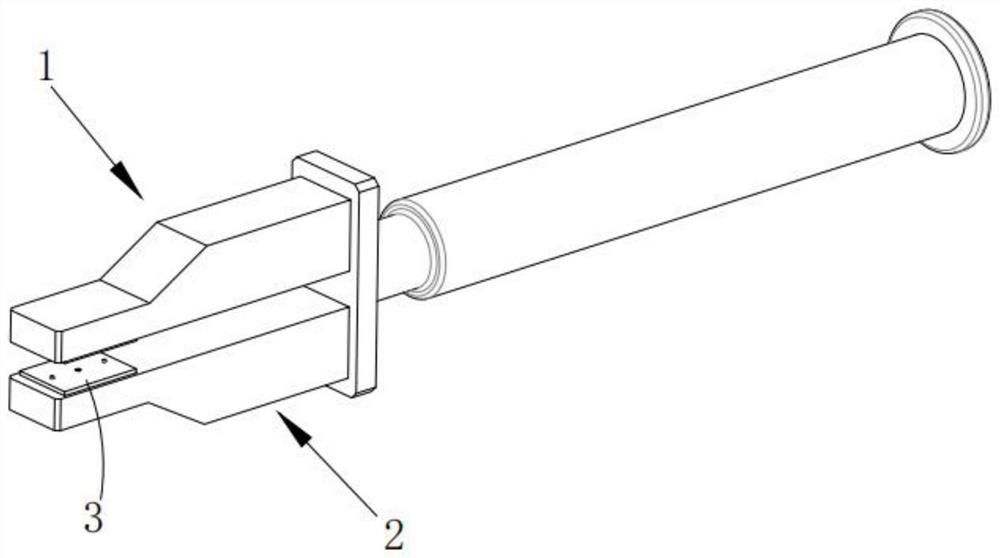
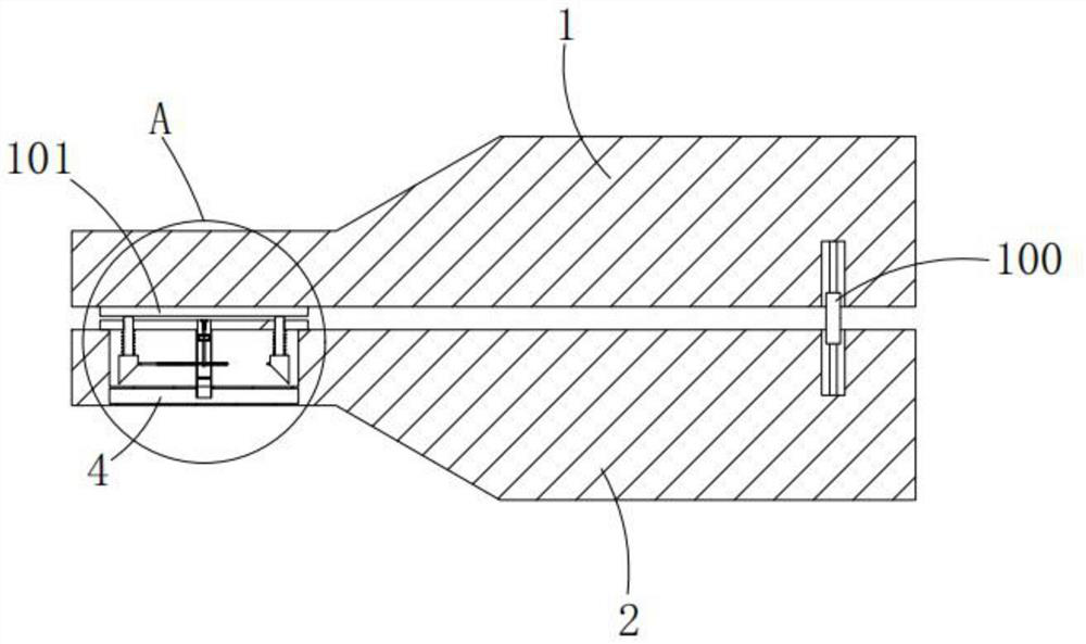
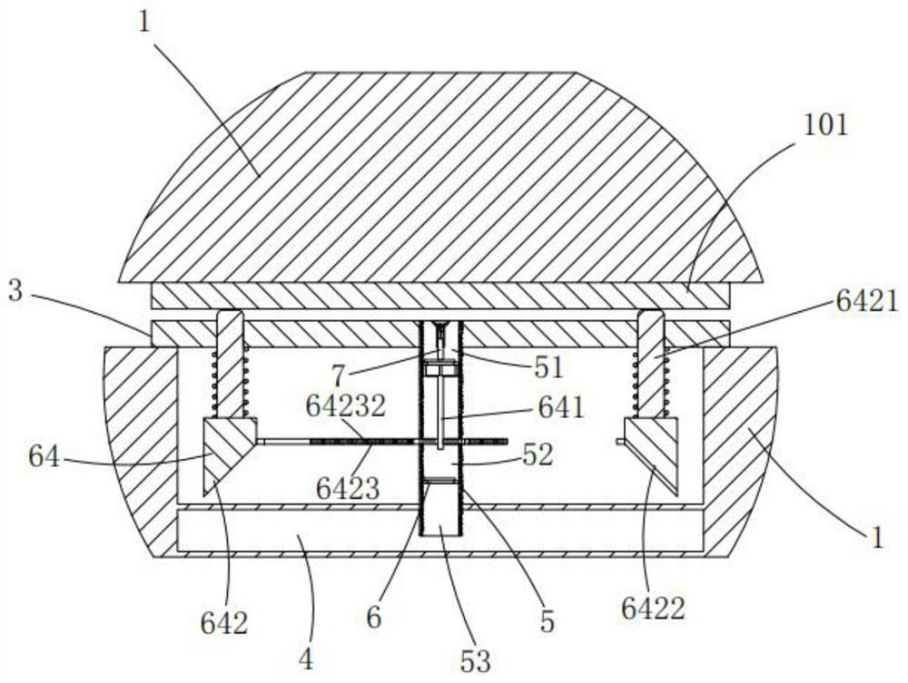
[0037] like Figure 1 to Figure 3 As shown in the figure, a high-efficiency LED lamp chip soldering device based on digital linear dimming technology includes an upper collet 1 and a lower collet 2 that can be clamped and arranged, and the lower collet 2 is provided with a welding device for placing chips. Stage 3, a tin storage chamber 4 is arranged below the welding stage 3, and also includes:

[0038] A tin supply channel 5, the tin supply channel 5 runs through the soldering station 3 and extends downward into the tin storage chamber 4;

[0039] The conveying device 6 is arranged in the tin conveying channel 5 and divides the tin conveying channel 5 into a storage section 51, a temporary storage section 52 and a conveying section 53 from top to bottom. The tin in the tin storage chamber 4 enters the storage section 51 through the conveying section 53 and the temporary storage section 52 in sequence;

[0040] The tin feeding device 7, the tin feeding device 7 sends the ti...


PUM


Abstract

The invention relates to a high-efficiency LED lamp chip soldering device based on digital linear dimming technology. A tin storage chamber is arranged below, and also includes a tin conveying channel, a conveying device and a tin conveying device. The tin conveying channel runs through the welding table and extends downward to the tin storage chamber; It is divided into a storage section, a temporary storage section and a conveying section. The conveying device makes the tin in the tin storage room enter the storage section through the conveying section and the temporary storage section in turn; the tin feeding device sends the tin in the storage section to the solder joints of the chip. The invention solves the technical problem that the molten tin is difficult to be sent to the welding point in the prior art.

Description

technical field [0001] The invention relates to LED chip processing equipment, in particular to a high-efficiency LED lamp chip soldering equipment based on digital linear dimming technology. Background technique [0002] At present, most of the traditional LED lamps on the market use electronic circuits to detect the amplitude of the input current in order to obtain different color temperatures to meet the needs of different light intensities in different occasions. Distributed to LED modules of different color temperatures, or by pulse width modulation, the LED current is chopped at a relatively high frequency, and the LED current is adjusted by the ratio between the on time and the switching period to obtain different color temperatures, which Both methods require a large number of components and complex logical relationships, in which the semiconductor chip is the heart of the LED lamp, one end of the chip is attached to a bracket, one end is the negative electrode, and ...

Claims


Application Information

Patent Timeline
Patent Type & Authority Patents(China)
IPC IPC(8): B23K3/06B23K3/08
CPCB23K3/0638B23K3/08B23K3/087
Inventor 姜如银戴福军项子豪
Owner 浙江凯友照明科技有限公司
Why Eureka
Try Eureka