Arm assembly for a crash test dummy

a technology for crash test dummies and arm assemblies, which is applied in the direction of instruments, structural/machine measurement, educational models, etc., can solve the problems of difficult to simulate accurate results of an injury to a living occupant, and the test is not always accura

Inactive Publication Date: 2005-03-31
HYUNDAI MOTOR CO LTD
View PDF10 Cites 19 Cited by
  • Summary
  • Abstract
  • Description
  • Claims
  • Application Information

AI Technical Summary

Problems solved by technology

Such a conventional arm assembly cannot accurately realize a force of a human arm, therefore, results of the test are not always accurate.
Because the fingers of the dummy are fixed to the wheel, it is difficult to simulate accurate results of an injury to a living occupant because the fingers do not realize a grasping force of a human hand.

Method used


Image

  • Arm assembly for a crash test dummy
  • Arm assembly for a crash test dummy
  • Arm assembly for a crash test dummy

Examples


Embodiment Construction

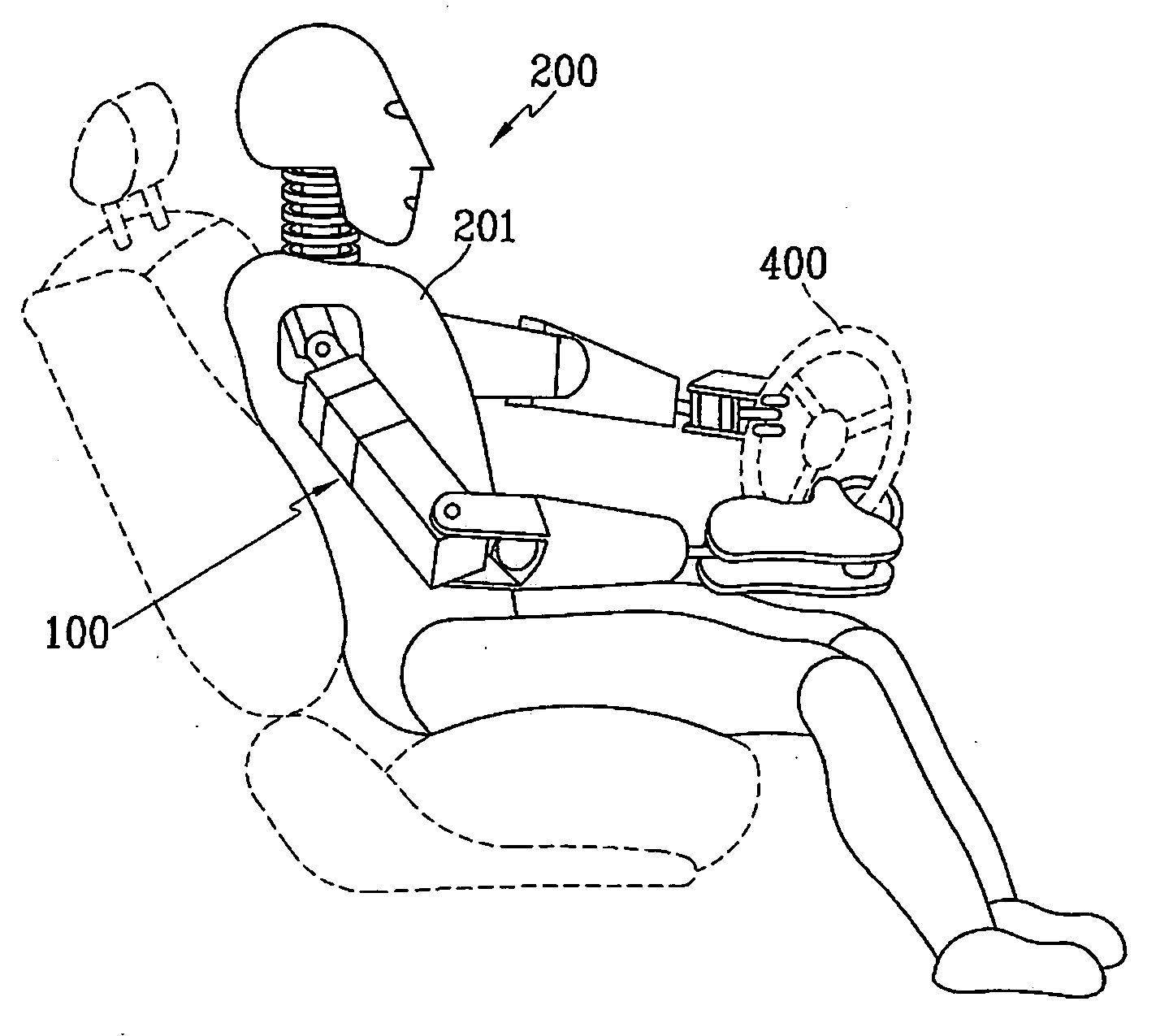
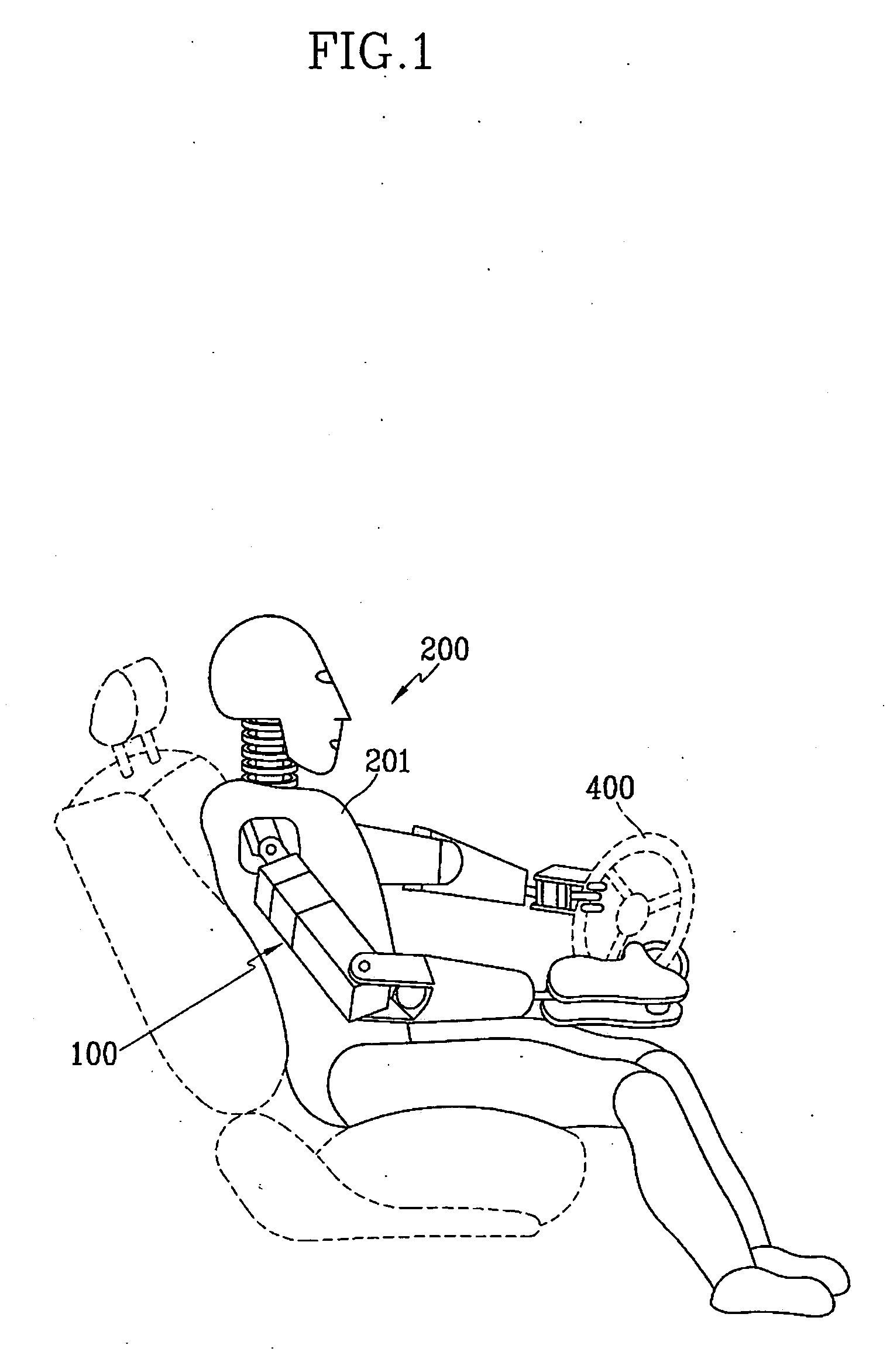
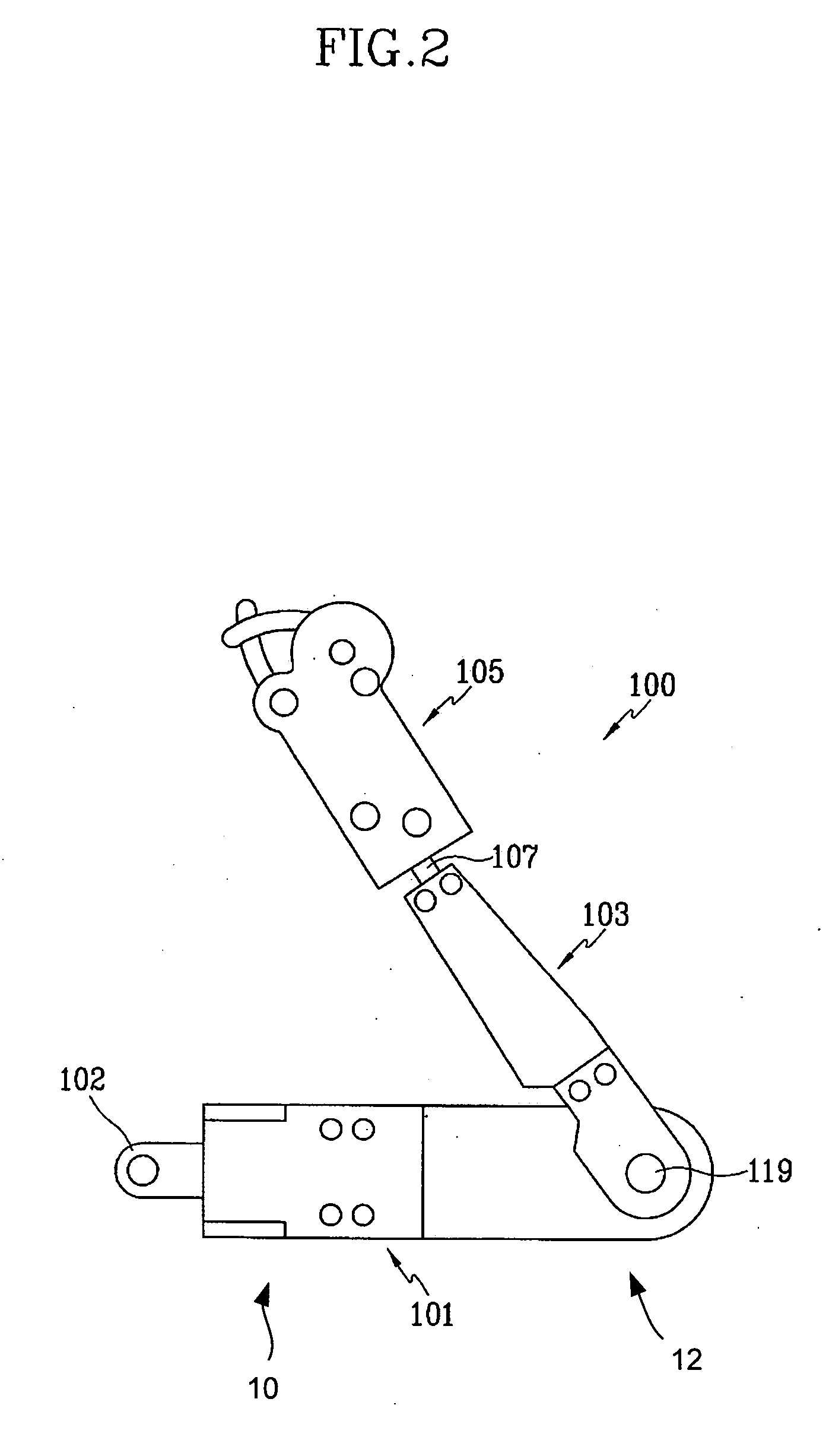
[0024] As shown in FIGS. 1 and 2, an arm assembly 100 for a crash test dummy 200 includes an upper arm unit 101 and a lower arm unit 103. An upper end portion 10 of the upper arm unit 101 is pivotally connected to a body 201 of the crash test dummy 200 through a link portion 102. Preferably, a pivotal motion of the upper arm unit 101 with respect to the body 201 of the crash test dummy 200 is allowed within a predetermined range. The lower arm unit 103 is pivotally connected to a lower end portion 12 of the upper arm unit 101. A hand unit 105 is connected to the lower arm unit 103 through a wrist joint 107.

[0025] According to FIG. 3, the upper arm unit 101 includes a housing 109 and a driving device 111. The driving device 111 is disposed inside the housing 109 and the driving device 111 drives the lower arm unit 103 to undergo pivotal motions. It is preferable that the driving device 111 includes a motor 113 and a gear unit 115 connected to the motor 113. The motor 113 is controll...


PUM

PropertyMeasurementUnit
forceaaaaaaaaaa
elasticaaaaaaaaaa
frictionaaaaaaaaaa

Abstract

An arm assembly for a crash test dummy includes an upper arm unit, a lower arm unit, a wrist joint, and a hand unit. An upper portion of the upper arm unit is connected to a body of the crash test dummy. The lower arm unit is pivotally connected to a lower portion of the upper arm unit. A first end of the wrist joint is rotatably connected to the lower arm unit. The hand unit is pivotally connected to a second end of the wrist joint. The upper arm unit comprises a housing and a driving device disposed in the housing. The driving device drives the lower arm unit.

Description

CROSS-REFERENCE TO RELATED APPLICATIONS [0001] This application claims priority of Korean Application No. 10-2003-0066538, filed on Sep. 25, 2003, the disclosure of which is incorporated fully herein by reference. FIELD OF THE INVENTION [0002] Generally, the present invention relates to an automobile crash test dummy. More particularly, the crash test dummy includes a novel arm assembly for a crash test dummy. BACKGROUND OF THE INVENTION [0003] Crash test dummies are widely used in vehicle crash tests to simulate injury to an occupant. A conventional arm assembly of a crash test dummy includes an upper arm portion, a lower arm portion, and a hand portion. These portions are generally connected together through universal joints. Such a conventional arm assembly cannot accurately realize a force of a human arm, therefore, results of the test are not always accurate. [0004] Furthermore, fingers of the hand unit are generally fixed to a steering wheel with a fixing means such as tape du...

Claims


Application Information

Patent Timeline
Patent Type & Authority Applications(United States)
IPC IPC(8): G01M17/007G01M7/08G09B23/32
CPCG09B23/32G01M7/08
Inventor CHOI, SEONG CHULL
Owner HYUNDAI MOTOR CO LTD
Why Eureka
Try Eureka