
Arrow system

a technology of arrow shafts and arrows, applied in the field of arrow systems, can solve the problems of low circumferential or arrows cannot withstand, and the hoop strength of these arrow shafts was so low, and achieve the effect of assisting with point alignmen

Inactive Publication Date: 2005-04-07
JAMES D EASTON
View PDF22 Cites 2 Cited by
  • Summary
  • Abstract
  • Description
  • Claims
  • Application Information

AI Technical Summary

Benefits of technology

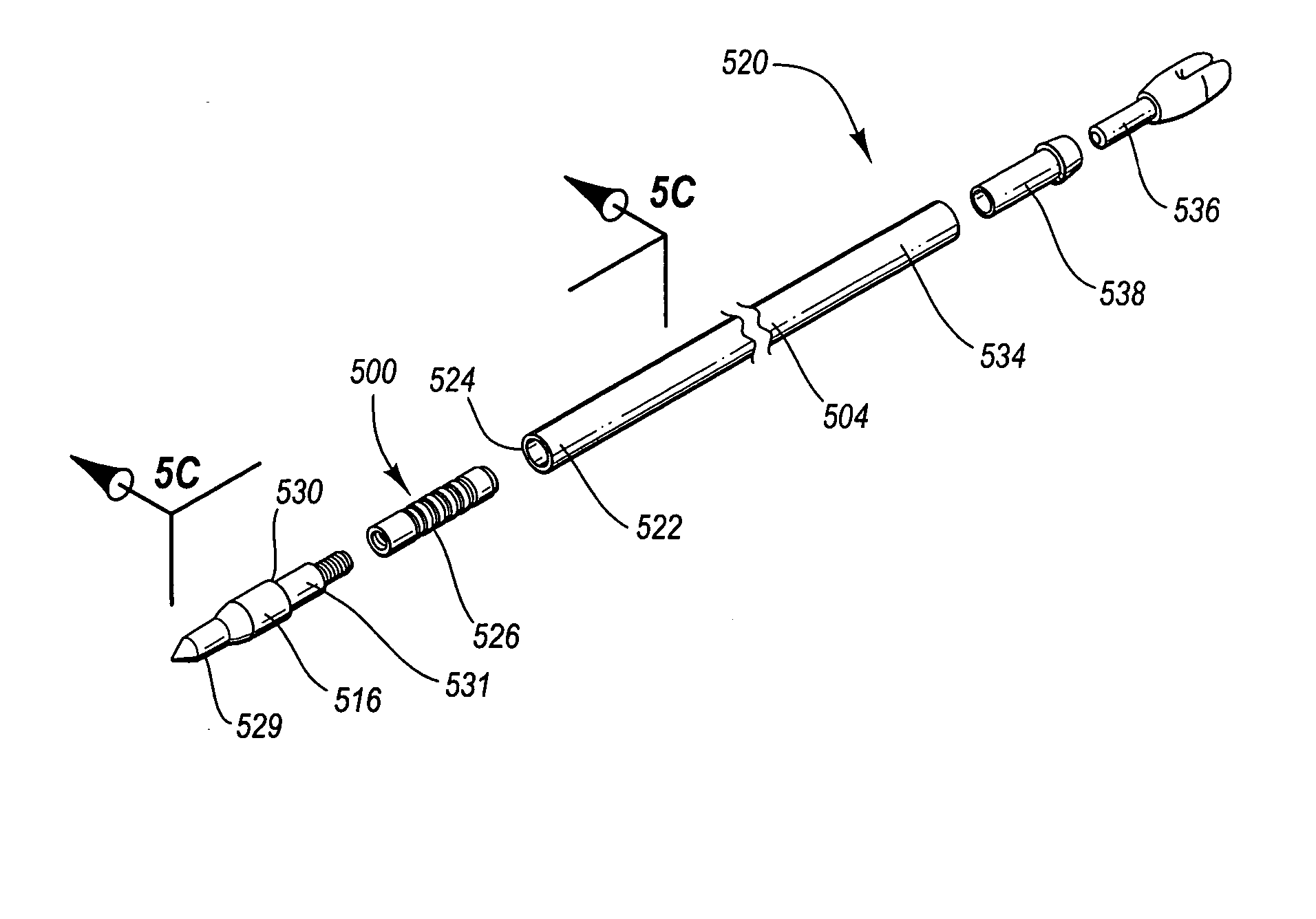
[0013] The present invention comprises an arrow including a shaft with a first end and an insert receptive of a point, the insert being disposed completely within the first end of the shaft. Hunters commonly use field points for practice and broadheads (either expandable or fixed-blade) for hunting. Although this aspect of the present invention (i.e., an internal component small outside diameter arrow shaft and a novel insert installation system) is advantageous when field points are used, the invention is particularly advantageous when using broadheads because broadheads exacerbate many shaft / insert / point alignment problems.
[0015] Another embodiment comprises an arrow including a shaft having an inside diameter, a first end, and a first end wall, and a point having a head, a shoulder, and a shank, where the shoulder of the point bears directly against the first end wall and the shank fits snugly inside the arrow shaft and bears against the inside surface of the arrow shaft. The direct contact between the point and arrow shaft improves alignment between these two components. In this embodiment, the insert is disposed completely inside the shaft and the point is threadedly received by the insert.
[0025] Another aspect of the invention involves a method of coupling a point to an arrow shaft including inserting an entire point insert into the arrow shaft and fastening the point to the point insert. According to this method, the point includes a shoulder and a shank, where the shoulder directly engages an end wall of the arrow shaft and the shank directly engages the inside surface of the arrow shaft, all of which assists with point alignment.

Problems solved by technology

Prior designs and processes for constructing FRP shafts resulted in a low circumferential or hoop strength.
The hoop strength of these arrow shafts was so low that the arrows could not withstand even small internal loads applied in a direction radially outwardly from the center of the shaft.
For example, internal loads generated from inserting standard components into the inside of these types of shafts would have resulted in failure of the arrow shaft.
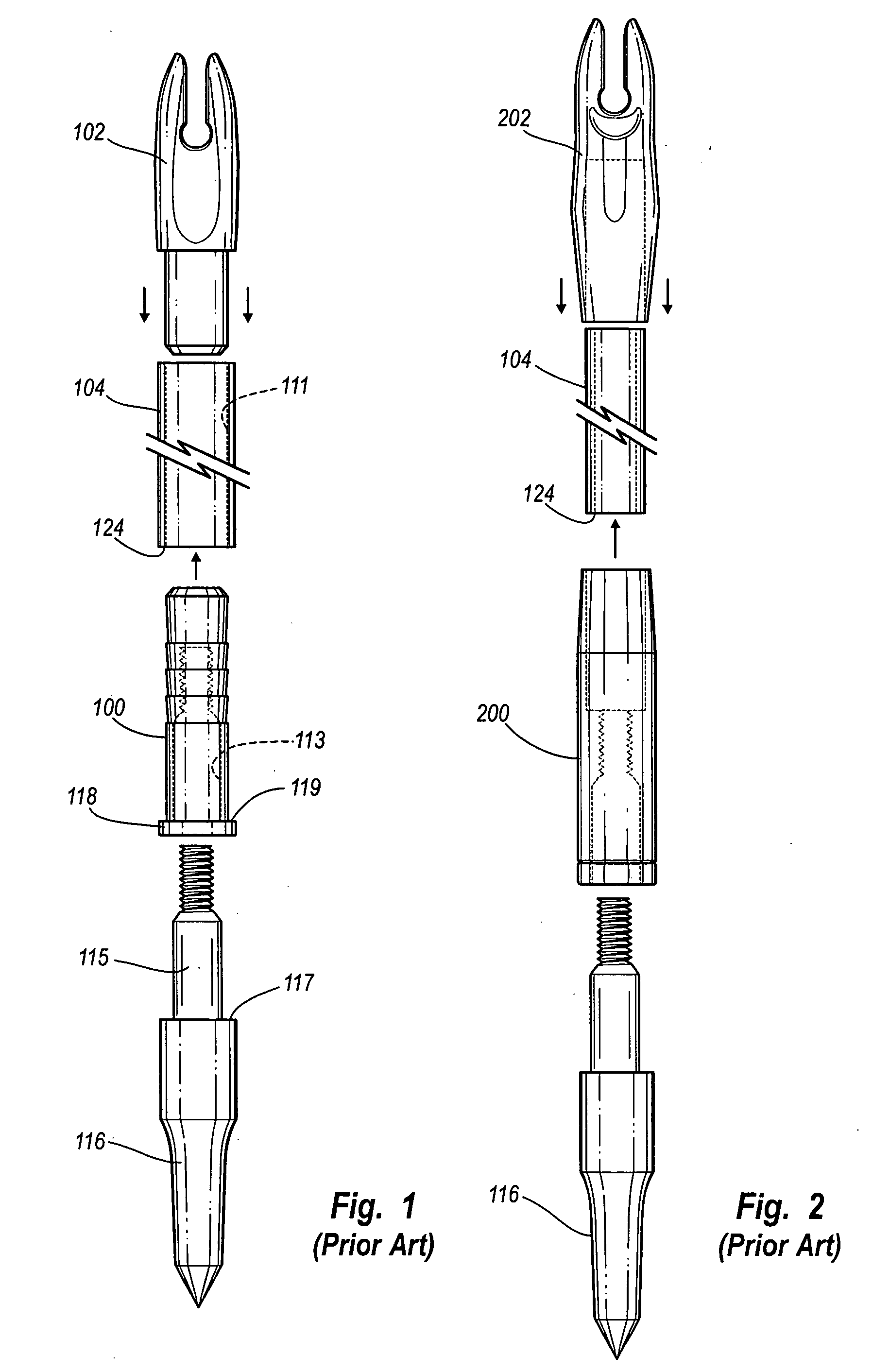
First, outsert nocks 202 have a feel that is objectionable to most archers.
Second, outsert nocks 202 frequently result in mechanical interference with many types of arrow rests when launching the arrow.
Contact between the nock outsert and the arrow rest can result in unpredictable disturbances during launch of the arrow, and therefore will affect the accuracy of the shot.
Third, the point outsert 200 has a larger diameter relative to the diameter of the shaft, which makes the arrows containing the point outsert 200 more difficult to extract from various targets as compared to arrows with insert components only.
Use of the point outsert 200 often results in damaged points and outserts 200, and further causes points and outserts 200 to detach from the arrow shaft and remain inside the target after the arrow is pulled from the target.
Points and / or outserts 200 lost inside a target may cause damage to subsequent arrows that happen to impact the target at the same location as the lost points or outserts.
Such higher velocities result in a flatter arrow trajectory.
This process of thinning the wall and increasing shaft diameter has, however, practical limitations.
At some point, if taken to an illogical extreme, the arrow would have mechanical properties similar to an aluminum beverage can with no practical resistance to side loads or crushing.
Half-out assemblies have, however, several disadvantages and have not been well accepted.

Method used


Image

  • Arrow system
  • Arrow system
  • Arrow system

Examples


Embodiment Construction

[0071] The present specification describes a novel arrow system that may be used for archery, and particularly for bowhunting. One aspect of the novel arrow system relates to a reduced diameter hunting arrow. The reduction in diameter of a hunting arrow facilitates more accurate shooting and better penetration than previous arrows. The reduced diameter hunting arrow may be sized to accommodate standard arrow point assemblies, half-out arrow point assemblies, or smaller diameter arrow point assemblies. The reduced diameter hunting arrow may also be used to accommodate a new point insert system and a new arrow point assembly, both of which are further described below. The novel arrow system also involves an insert installation tool to facilitate placement of the novel insert into an arrow shaft and an arrow shaft preparation tool to ensure the shaft will properly accommodate a point.

[0072] Accordingly, the specification describes various aspects of the invention according to the foll...


PUM


Abstract

The invention is directed to an arrow system having a shaft having a first end and an insert receptive of a standard point, the insert being disposed completely within the first end of the shaft. An insert installation tool may be used as part of the invention to facilitate insertion of the insert into the first end of the shaft. The invention further includes a reduced diameter hunting arrow shaft that maintains sufficient spine and weight characteristics. The reduced diameter hunting arrow shaft is receptive of standard or non-standard internal components for increasing arrow penetration and shot accuracy. Still further, the invention includes an arrow tip assembly including a male insert and a female point to assist in aligning points with arrow shafts. The arrow shaft is in one embodiment an aluminum-carbon arrow which includes a metallic core and an outer fiber reinforced polymer layer.

Description

RELATED APPLICATIONS [0001] This is a continuation-in-part of U.S. application Ser. No. 10 / 678,821 filed Oct. 3, 2003.TECHNICAL FIELD [0002] This invention relates to arrow systems, including in particular hunting arrow systems. BACKGROUND OF THE INVENTION [0003] Many different types of arrows and arrow shafts are known for use in hunting and sport archery. Two arrow types of relatively recent design are the fiber reinforced polymer (FRP) arrows and the aluminum arrows wrapped with fiber reinforced polymer. FRP is a generic term including, but not limited to, fiberglass composites and carbon fiber composites. Aluminum arrow shafts covered with fiber reinforced polymer are usually made of an aluminum core covered with carbon fiber and are often referred to as aluminum carbon composite (ACC) arrows, although any fiber reinforced polymer may be used as the covering. Traditional FRP and ACC shafts have been produced by a number of different manufacturing processes. The first FRP arrow s...

Claims


Application Information

Patent Timeline
IPC IPC(8): F42B6/04F42B6/06
CPCF42B6/08F42B6/04
Inventor PALOMAKI, TEDDY D.ROWSELL, EDWIN A.
Owner JAMES D EASTON
Learn More