
Systems and methods for delivering a medical implant to an anatomical location in a patient

Active Publication Date: 2005-04-07
BOSTON SCI SCIMED INC
View PDF78 Cites 149 Cited by
  • Summary
  • Abstract
  • Description
  • Claims
  • Application Information

AI Technical Summary

Benefits of technology

[0011] According to one embodiment, the knitted mesh is free floating within the sleeve. For one configuration of this embodiment, an opening, located at a midpoint of a top portion of the sleeve, exposes the entire width of the knitted mesh. Preferably, the knitted mesh is made of polypropylene, is about 1 cm in width and about 45 cm in length, and terminates at free ends. According to one configuration, the entire length of the knitted mesh, including both free ends, does not connect to the sleeve or anything else. This feature enables a medical operator to pull on the ends of the sleeve during sling assembly placement, for example, via the dilators, the association loops, and/or the delivery devices, without risk of stretching, curling, or otherwise deforming the knitted mesh.
[0012] According to another feature, a tabbed spacer is located at a midpoint of a bottom side of the sleeve, and encloses a looped portion

Problems solved by technology

However, one deficiency that such conventional procedures suffer f

Method used


Image

  • Systems and methods for delivering a medical implant to an anatomical location in a patient
  • Systems and methods for delivering a medical implant to an anatomical location in a patient
  • Systems and methods for delivering a medical implant to an anatomical location in a patient

Examples


Example

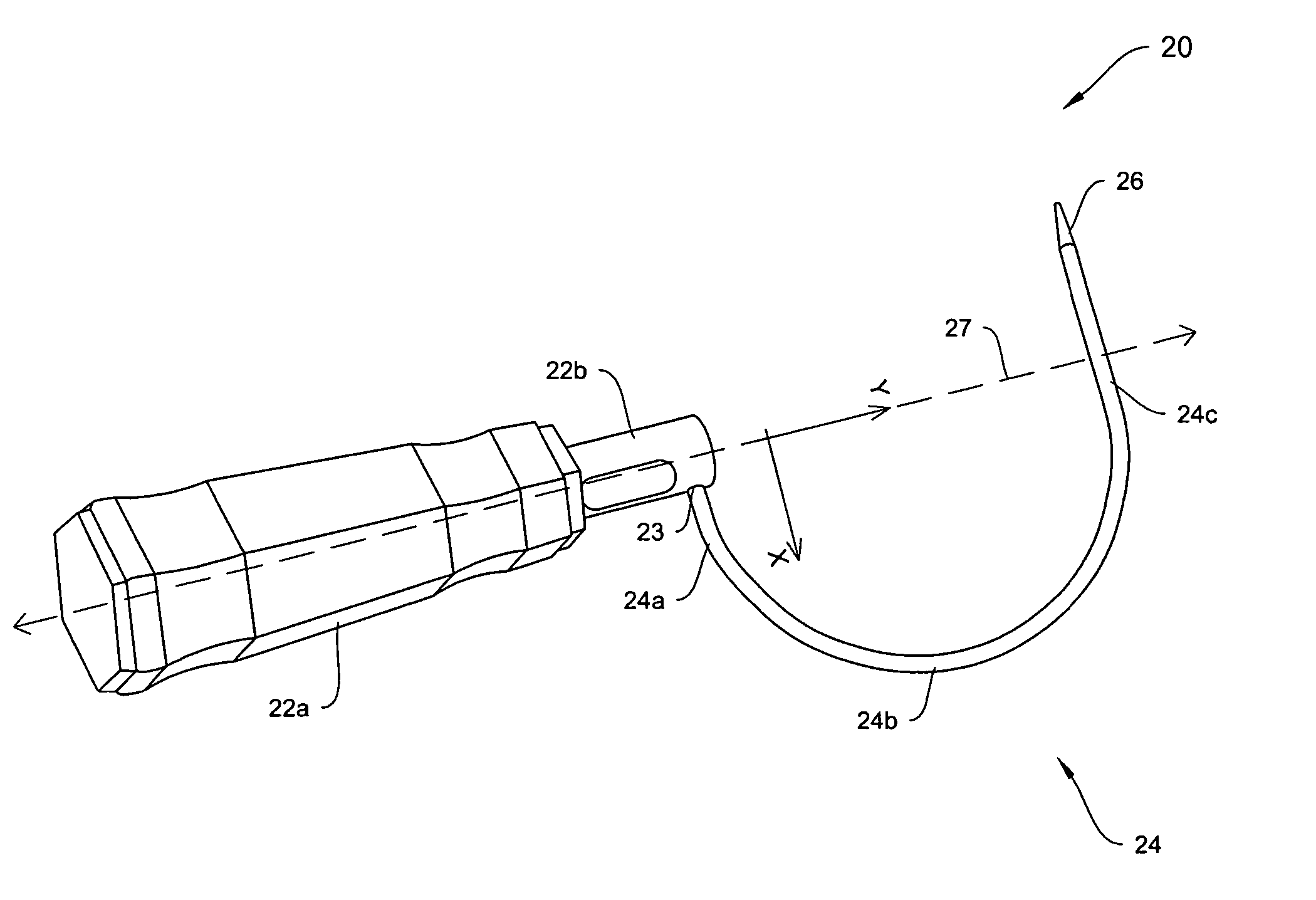
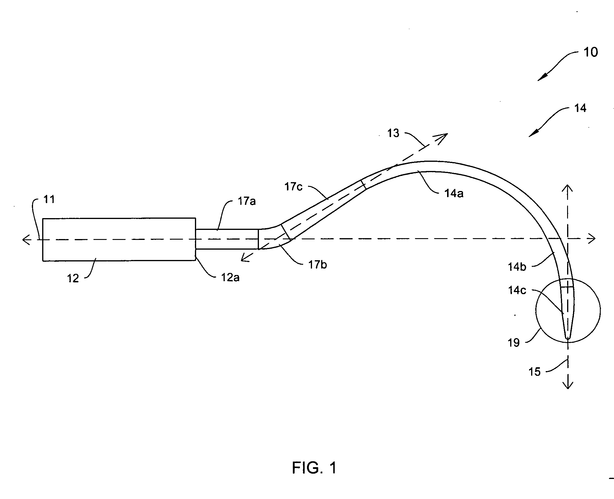
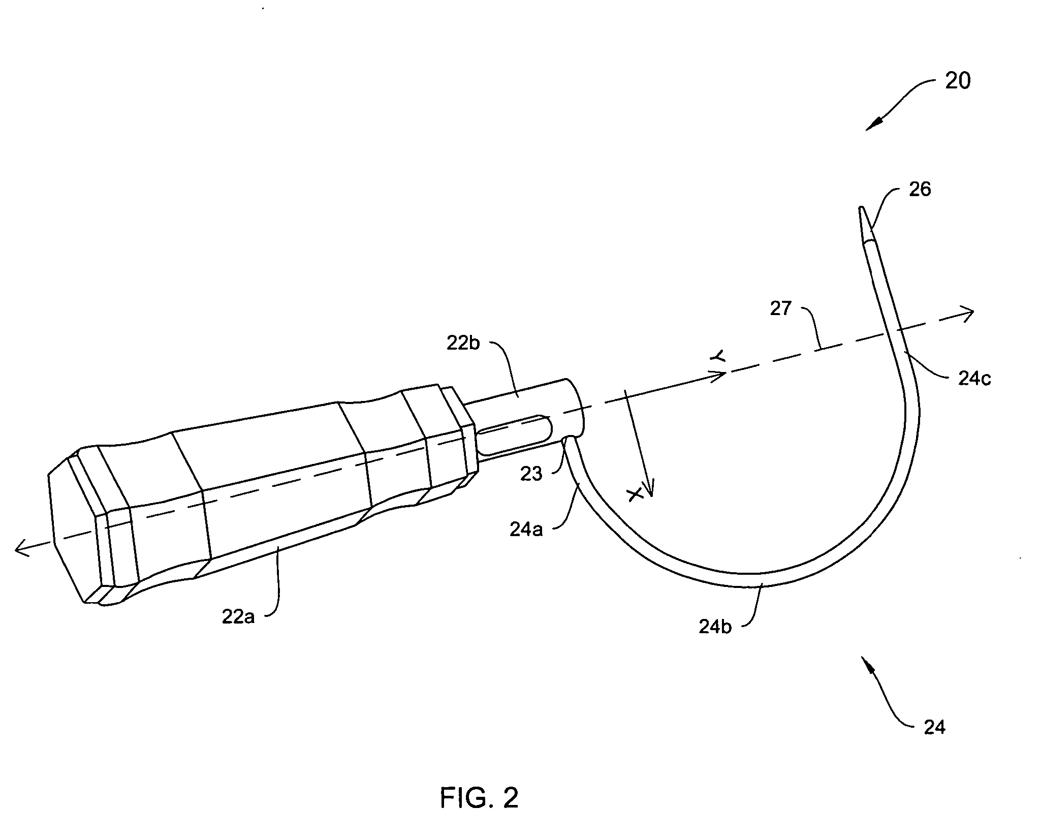
[0055] As described in summary above, the invention, in one illustrative embodiment, relates to systems and methods for delivering and placing a medical implant at an anatomical site in the body of a mammal. In particular, in various illustrative examples, the invention provides delivery devices, systems, and methods for placing an implant, e.g., a sling for treating UI (including SUI), by a trans-obturator approach. In one aspect, the implant includes a supportive sling and is delivered to the periurethral tissue of a patient via the obturator foramen. In one embodiment, the delivery device includes a handle and a shaft extending from a distal end of the handle. The patient may be either a female patient or a male patient.

[0056] Without limitation, examples of slings, sling assemblies, delivery devices and implantation approaches that may be employed with respect to some features of illustrative embodiments of the invention are disclosed in U.S. Pat. No. 6,666,817, entitled “Expan...


PUM


Abstract

Medical implant delivery devices and systems are disclosed. In general, an exemplary delivery device comprises a shaft and a handle. An exemplary system includes any number of the following: a delivery device, a sling assembly, guide members, and connectors that interconnect the above. Embodiments of all the above components and their combinations are disclosed. Methods of using the above system in trans-obturator approaches are disclosed.

Description

CROSS REFERENCE TO RELATED APPLICATIONS [0001] This application claims the benefit of and priority to U.S. Provisional Patent Application Ser. No. 60 / 508,600 filed on Oct. 3, 2003 and U.S. Provisional Patent Application Ser. No. 60 / 569,300, filed on May 6, 2004, which are hereby incorporated by reference in their entirety.FIELD OF THE INVENTION [0002] The invention generally relates to systems and methods for delivering a medical implant to an anatomical location in a patient. More particularly, in various embodiments, the invention relates to systems and methods for employing a trans-obturator approach for delivering a medical implant to the periurethral tissue of a patient. BACKGROUND OF THE INVENTION [0003] Urinary incontinence (“UI”) occurs in both men and women. Various types of incontinence are caused by different conditions and call for different treatments. For example, stress urinary incontinence (“SUI”) is known to be caused by at least two conditions, intrinsic sphincter ...

Claims


Application Information

Patent Timeline
IPC IPC(8): A61B17/00A61B17/04A61B17/06A61B17/28A61F2/00
CPCA61B17/06109A61B2017/0046A61B2017/00805A61B2017/06009A61B2017/06019A61F2/0045A61B2017/06076A61B2017/0608A61B2017/06085A61B2017/2927A61B2017/06042A61F2/0063A61F2002/0072
Inventor CHU, MICHAEL S. H.INTOCCIA, ALFRED P. JR.MOORE, TIM
Owner BOSTON SCI SCIMED INC
Learn More