Depthometer

a depthometer and depth measurement technology, applied in the direction of measuring wheels, surveying, borehole/well accessories, etc., can solve the problems of physical contact between users and lines, difficulty in determining the length of the cable lowered into the well, and inability to identify features on the cabl

Inactive Publication Date: 2005-04-14
ROBERTS DANNY
View PDF29 Cites 4 Cited by
  • Summary
  • Abstract
  • Description
  • Claims
  • Application Information

AI Technical Summary

Problems solved by technology

The lack of identifying features on a cable render measurement of the length of cable lowered into the well difficult to determine from the position of the wellhead, or well opening.
Also, safety regulations limit physical contact between users and lines lowered into a well, as well as with instruments or mechanisms attached to, or engaged with lines.
There has not, however, been a concurrent alteration to the design of depthometers to comply with revised operating and safety procedures.
One difficulty that arises when using depthometers is the obstruction caused by the wellhead lubricator.
While this position provides the user improved access to the depthometer, the depthometer measurement output is presented to the user upside-down or in another position obstructing the ability of the user to read the output.
Further, the depthometer must often be held by hand when positioned at the draw-works drum to obtain a reliable measurement, in violation of safety precautions.
To complicate this situation, most depthometers do not securely engage the main measurement wheel to the line.
Consequently, movement of the line or a slight pull on the depthometer often disengages the wheel from the line resulting in unreliable measurements.
When mounting a depthometer in proximity to the cable drum, placing the depthometer on a stand or securing it by tether is impractical.
Further, when the depthometer is tethered in proximity to the drum, the weight of the depthometer tends to pull the main wheel away from the line thereby disengaging the instrument from the line.
Other difficulties with conventional depthometers include open spokes on main measuring wheels which can injure fingers if placed too close in proximity; awkward installation procedures of the depthometer upon the line; damage to the counter due to accumulated debris in open gear components; and broken or damaged idler arms that hold idler wheels due to fatigue and misalignment.

Method used


Image

  • Depthometer
  • Depthometer
  • Depthometer

Examples


Embodiment Construction

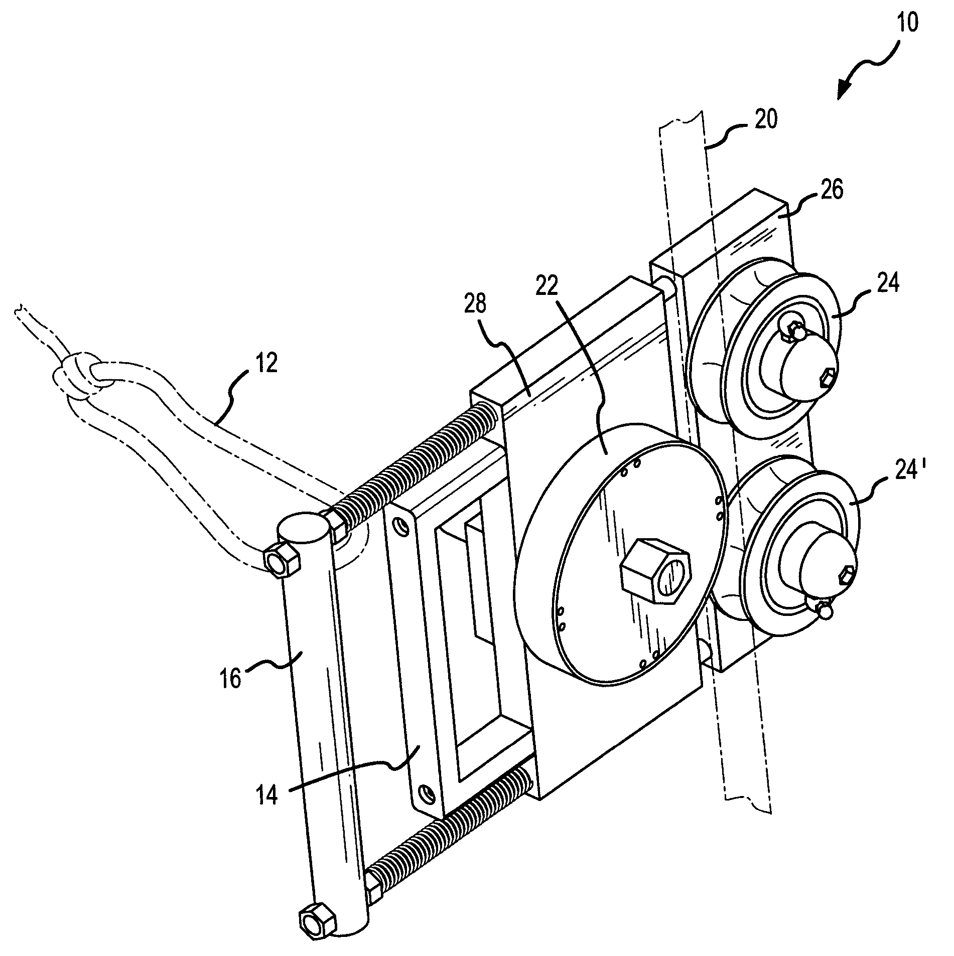
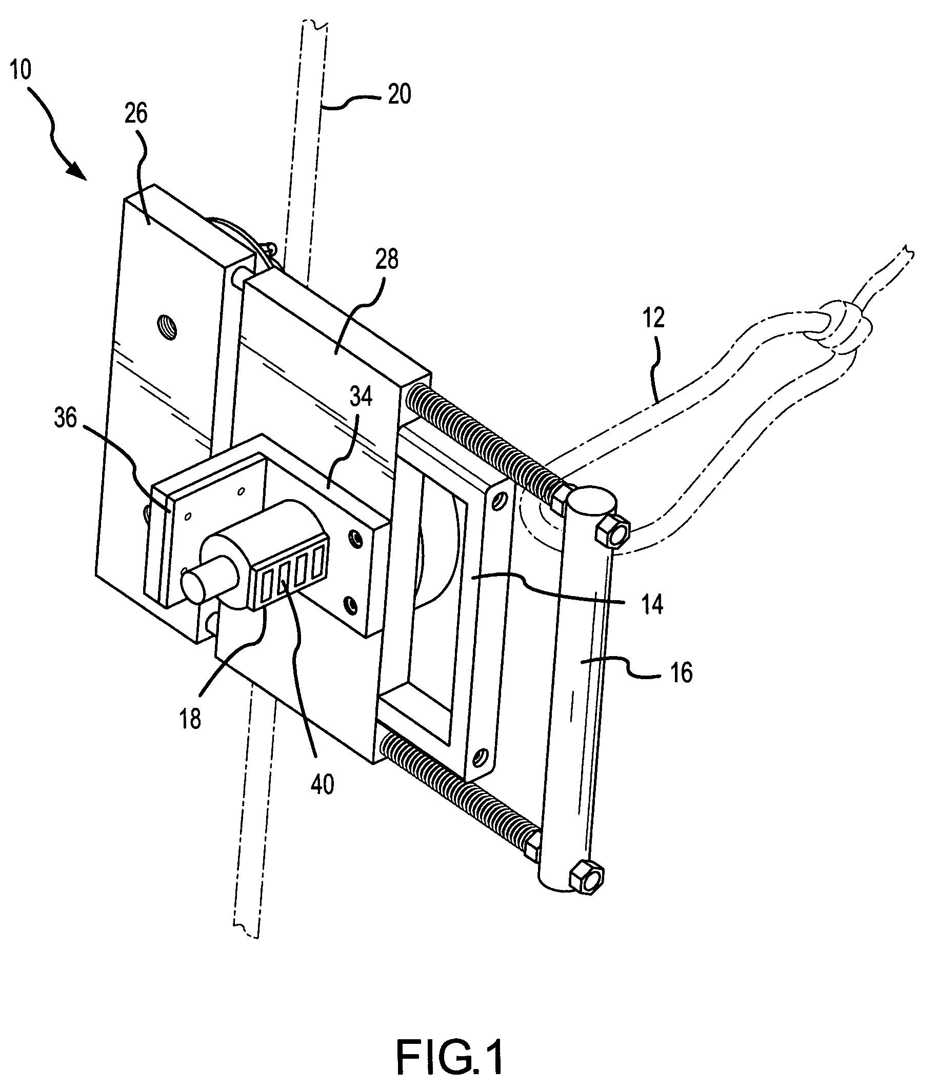
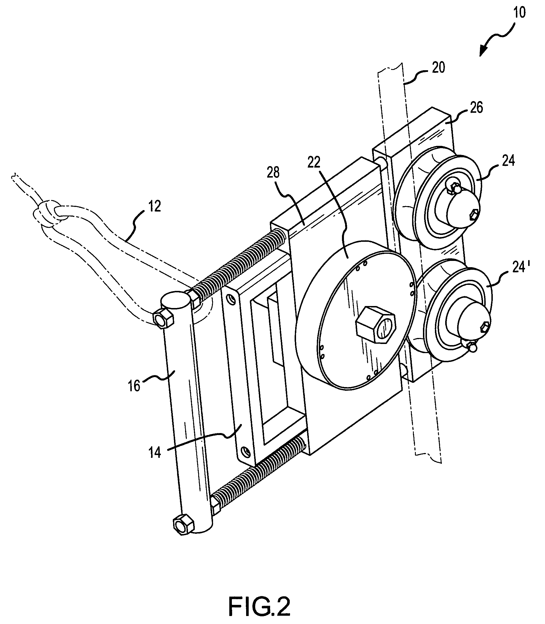
[0025]FIGS. 1, 2 and 3 provide an overview of the operation of depthometer 10 used for measuring a length of an elongate line. Referring to FIG. 1, a perspective front view of depthometer 10 installed upon an elongate line 20 for measuring a length of line 20 is shown. Depthometer 10 engages line 20 in a secure manner when in the installed position.

[0026] First, or inner, handle 14 is used in conjunction with second, or outer, handle 16 to open and close two adjacent and opposing body components, 26 and 28, of the body of depthometer 10 that serve as means for mounting line guides and a wheel. Inner handle 14 and outer handle 16 additionally provide a means for grasping the depthometer 10. When a user grasps inner handle 14 and outer handle 16 and squeezes inner handle 14 towards outer handle 16, first, or main, body component 28 of depthometer 10 is displaced from second, or lower, body component 26. This displacement produces a gap between the body components, wherein a user posi...


PUM


Abstract

A depthometer for measuring a length of an elongate line. A main wheel is mounted upon a main body component and is in communication with a registering mechanism. Line guides are mounted upon a lower body component. An inner handle connected to the main body component is pulled toward an outer handle connected to the lower body component, in opposition to a spring-like force in the opposite direction, to open the depthometer and position a line within the depthometer. The main body component is automatically moved towards the lower body component via a spring-like force when the inner handle is released, thereby engaging the line in the depthometer in the installed position.

Description

BACKGROUND OF THE INVENTION [0001] 1. Field of the Invention (Technical Field) [0002] The present invention relates generally to the field of instruments used for measuring distances. In particular, the present invention relates to instruments for measuring a length of an elongate line. [0003] 2. Background Art [0004] In the well drilling industry cables or wires are lowered into the well for determining well depths. The lack of identifying features on a cable render measurement of the length of cable lowered into the well difficult to determine from the position of the wellhead, or well opening. An early method of measurement commonly referred to as “stringing in” utilized a predefined length of cord to measure the length of cable entering a well, one predefined length at a time, until the desired maximum depth was reached. [0005] Since that time wheeled measuring tools and others, commonly referred to as “depthometers”, have replaced the stringing in method as a more efficient mea...

Claims


Application Information

Patent Timeline
Patent Type & Authority Applications(United States)
IPC IPC(8): E21B47/04G01B3/12G01B5/04
CPCG01B5/043E21B47/04
Inventor ROBERTS, DANNY
Owner ROBERTS DANNY
Why Eureka
Try Eureka