Wrench having greater torque

Inactive Publication Date: 2005-04-14
HSIEN CHIH CHING
View PDF2 Cites 8 Cited by
  • Summary
  • Abstract
  • Description
  • Claims
  • Application Information

AI Technical Summary

Benefits of technology

[0012] A further objective of the present invention is to provide a wrench which produces the maximum torque

Problems solved by technology

Thus, the conventional wrench easily slips from the s

Method used


Image

  • Wrench having greater torque
  • Wrench having greater torque
  • Wrench having greater torque

Examples


Example

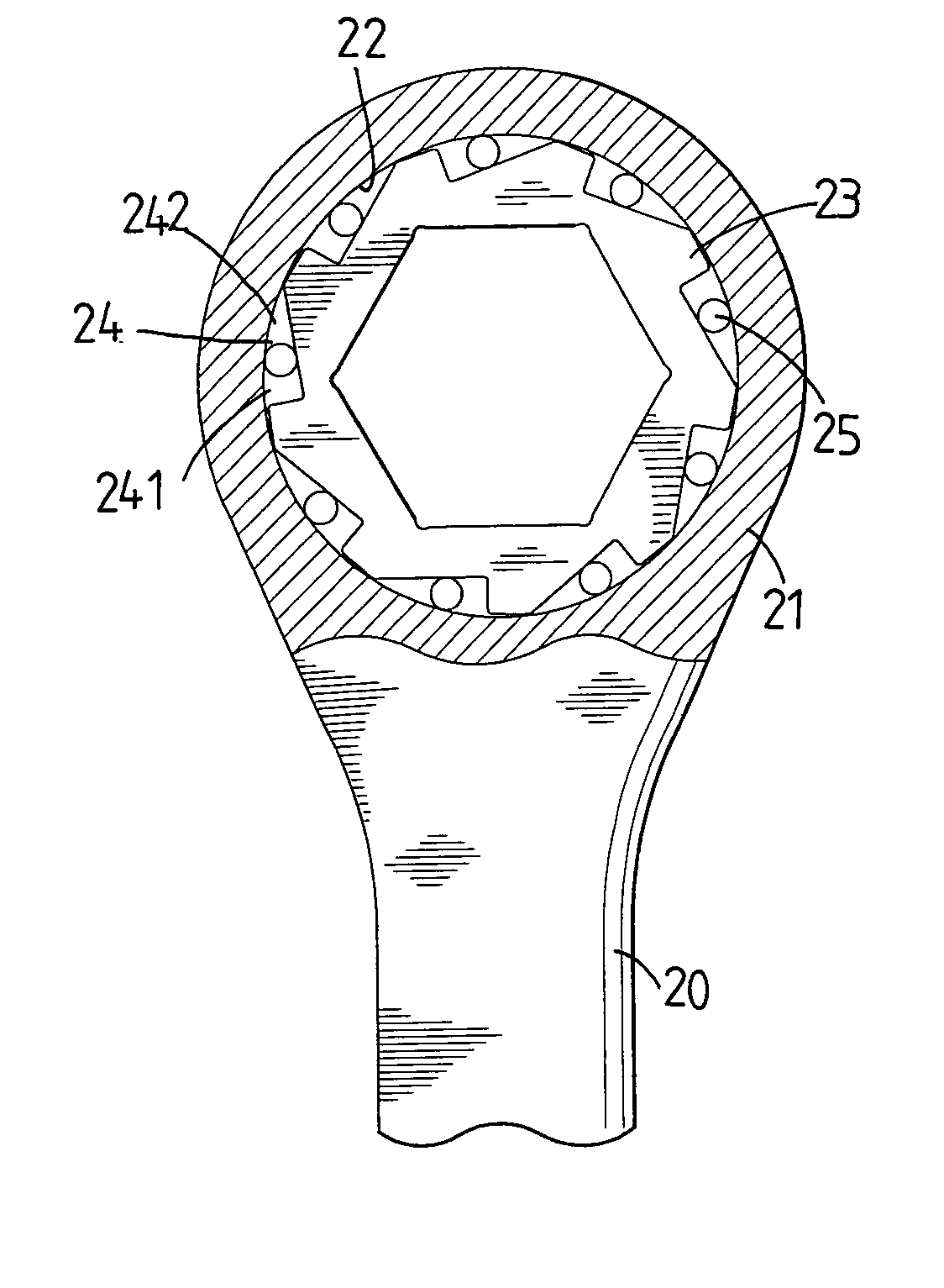
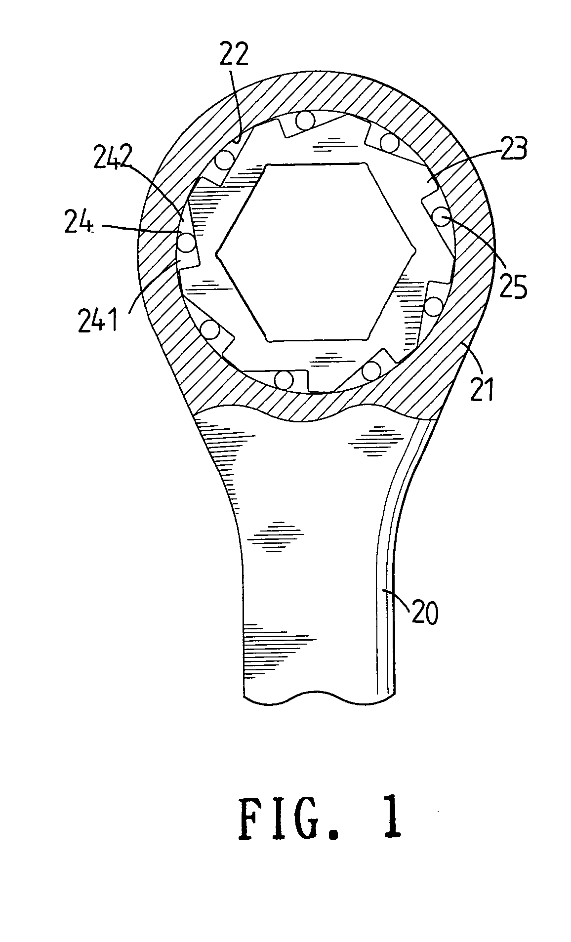
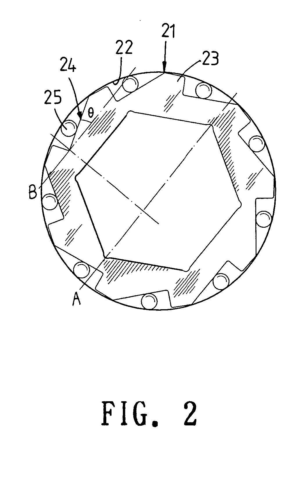
[0024] Referring to the drawings and initially to FIG. 1, a wrench in accordance with the preferred embodiment of the present invention comprises a wrench body 20 having an end formed with a drive portion 21 formed with a receiving portion 22, a ratchet wheel 23 mounted in the receiving portion 22 of the drive portion 21 and having a periphery formed with a plurality of oblique concave portions 24, and a plurality of rollers 25 each movably mounted in a respective one of the oblique concave portions 24 of the ratchet wheel 23 and each urged on a wall of the receiving portion 22 of the drive portion 21. Each of the oblique concave portions 24 of the ratchet wheel 23 has a first end formed with a deeper concave portion 241 and a second end formed with a shallower concave portion 242.

[0025] In operation, when the drive portion 21 of the wrench body 20 is rotated in the normal direction, each of the rollers 25 is rolled into the shallower concave portion 242 of a respective one of the ...


PUM


Abstract

A wrench includes a drive portion formed with a receiving portion, a ratchet wheel mounted in the receiving portion and formed with a plurality of oblique concave portions, and a plurality of rollers each movably mounted in a respective one of the oblique concave portions and each urged on a wall of the receiving portion. An included angle defined between a bottom face of each of the oblique concave portions and a horizontal line of the drive portion is ranged from 5 and 30 degrees. Thus, the resultant driving force of the wrench passes through the ratchet wheel having a greater thickness, so that the wrench produces the maximum torque during operation.

Description

BACKGROUND OF THE INVENTION [0001] 1. Field of the Invention [0002] The present invention relates to a wrench, and more particularly to a wrench having a greater torque. [0003] 2. Description of the Related Art [0004] A conventional wrench in accordance with the prior art shown in FIG. 5 comprises a wrench body 10 having an end formed with a drive portion 11 formed with a receiving portion 12, a ratchet wheel 13 mounted in the receiving portion 12 of the drive portion 11 and having a periphery formed with a plurality of oblique concave portions 14, and a plurality of rollers 15 each movably mounted in a respective one of the oblique concave portions 14 of the ratchet wheel 13 and each urged on a wall of the receiving portion 12 of the drive portion 11. Each of the oblique concave portions 14 of the ratchet wheel 13 has a first end formed with a deeper concave portion 141 and a second end formed with a shallower concave portion 142. [0005] In operation, when the drive portion 11 of t...

Claims


Application Information

Patent Timeline
IPC IPC(8): B25B13/46
CPCB25B13/462
Inventor HSIEN, CHIH-CHING
Owner HSIEN CHIH CHING
Why Eureka
Try Eureka