
Casing-type Charging module for mobile device

Active Publication Date: 2019-05-16
KOREA ELECTRONICS TECH INST
View PDF0 Cites 0 Cited by
  • Summary
  • Abstract
  • Description
  • Claims
  • Application Information

AI Technical Summary

Benefits of technology

The present invention provides a casing-type charging module for mobile devices that solves the problems of prior art. The module not only acts as a casing but also charges via an auxiliary battery mounted additionally on the casing. The module has a stable design that protects the rear surface of the mobile device even when the auxiliary battery is removed. The charging module has a coupling recess with an anti-slip member to prevent slipping. The assembly process is facilitated by integrating a portion protecting against impact, scratches, and flexural deformation. The first and second positioning guide protrusions prevent positional deviation in all directions.

Problems solved by technology

Such a mobile device requires a large consumption of battery power due to the provision of images or graphics through a large-sized liquid crystal display as described above, whereby the battery consumption may be accelerated.
However, with respect to a technique of charging the mobile device via the auxiliary battery while carrying it, since the auxiliary battery and the mobile device are separately provided from each other, there are disadvantages in that a separate charging cable must be additionally provided and it is inconvenient to grasp the auxiliary battery and the mobile device that are separated from each other at the same time.
However, since the above-described conventional techniques substantially have a structure that completely covers the rear surface of the mobile device, the rear surface design of the mobile device is not shown, thereby causing dissatisfaction of some users.
In other words, although the rear surface of the mobile device is recently designed such that it may best expose the characteristic of the mobile device, all the rear surface of the mobile device is covered by the auxiliary battery or the casing, resulting that user dissatisfaction may exist due to non-exposure of the rear surface design.
When the casing is made of a transparent material, there are disadvantages in that the auxiliary battery may not be stably coupled to the casing, the mobile device may not compliment a color of the mobile device, the casing of the transparent material is weak in strength, and it is not possible to protect against a flexural deformation of the mobile device.

Method used


Image

  • Casing-type Charging module for mobile device
  • Casing-type Charging module for mobile device
  • Casing-type Charging module for mobile device

Examples


Embodiment Construction

[0041]Hereinafter, a preferred embodiment of a casing-type charging module for a mobile device according to the present invention will be described with reference to FIGS. 1 to 12.

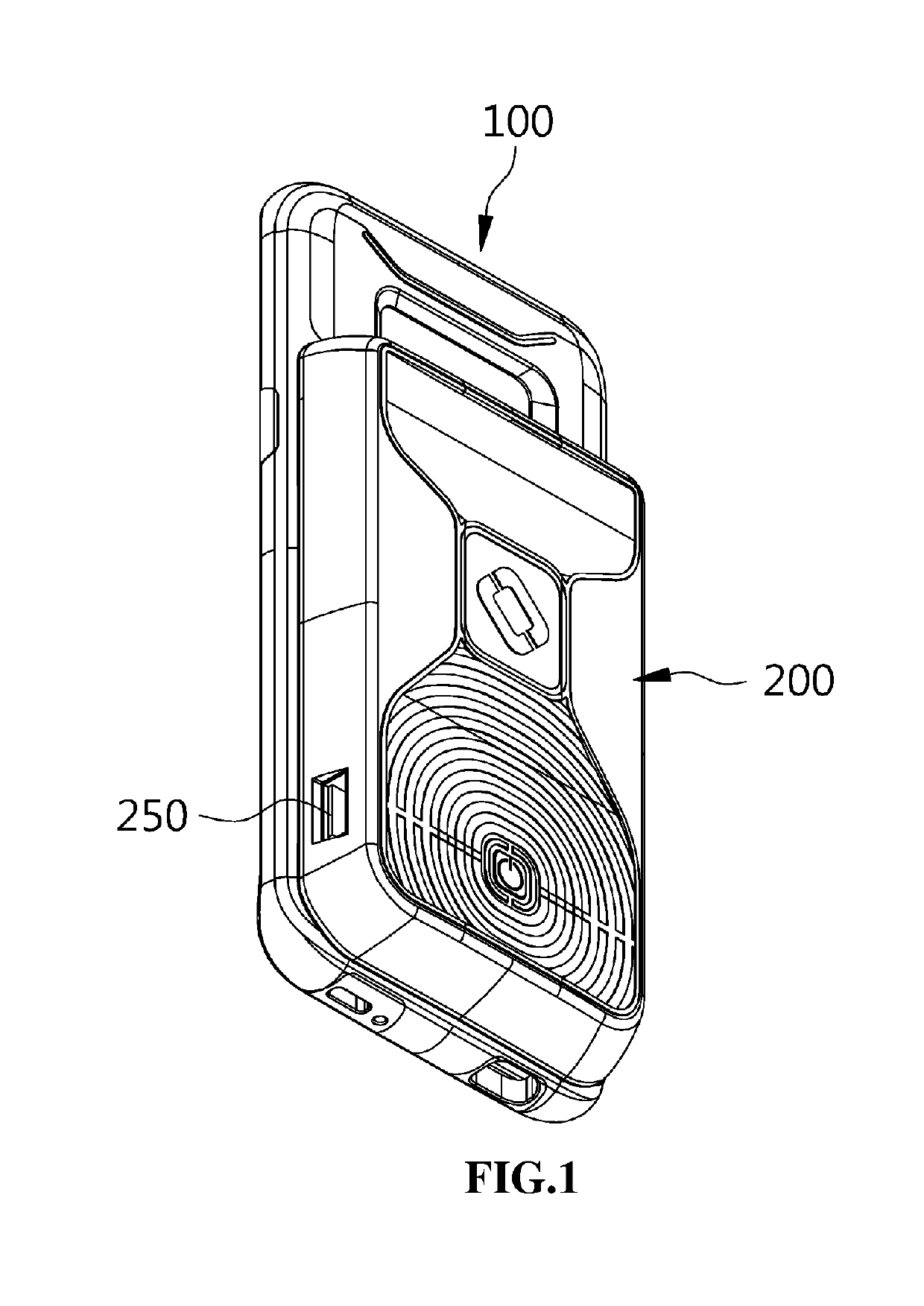
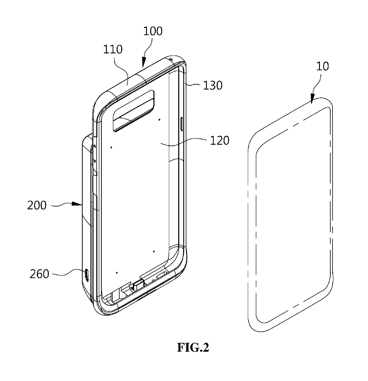
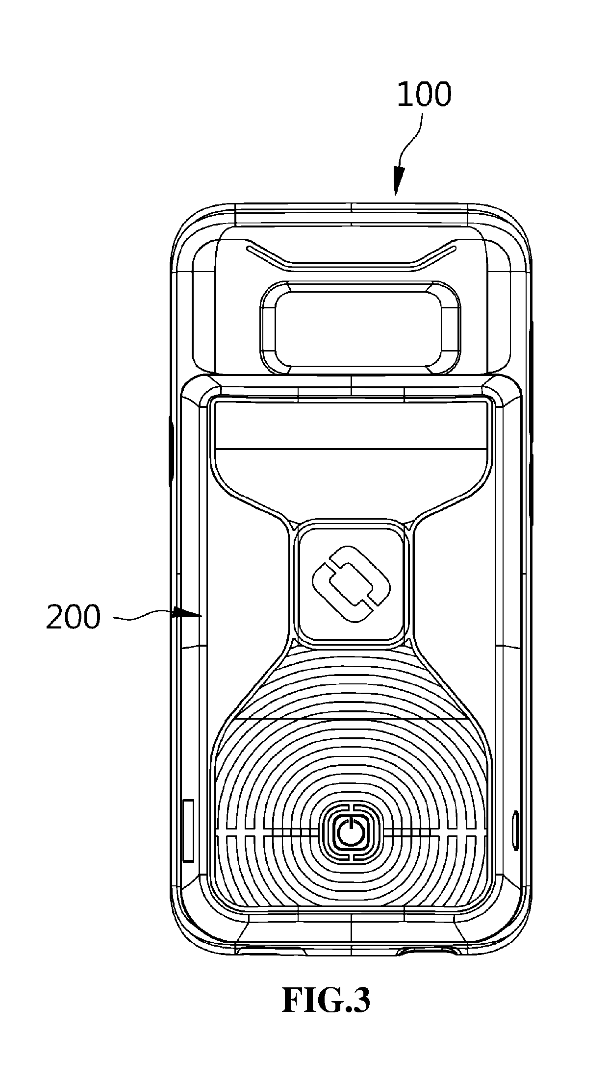
[0042]FIGS. 1 and 2 are perspective views of combined state viewing from directions different from each other to illustrate a casing-type charging module for a mobile device according to an embodiment of the present invention, FIG. 3 is a rear view illustrating a casing-type charging module for a mobile device according to an embodiment of the present invention, FIG. 4 is a front view illustrating a casing-type charging module for a mobile device according to an embodiment of the present invention, and FIG. 5 is a side view illustrating a casing-type charging module for a mobile device according to an embodiment of the present invention.

[0043]As shown in these drawings, a casing-type charging module for a mobile device according to an embodiment of the present invention includes a casing assembly 100 and a...


PUM


Abstract

Provided is a casing-type charging module for a mobile device including a casing assembly and a battery assembly. Particularly, the casing assembly may be stably coupled to the battery assembly even though a rear surface design of the mobile device is sufficiently exposed.

Description

BACKGROUND OF THE INVENTIONField of the Invention[0001]The present invention relates generally to a charging module for charging a mobile device. More particularly, the present invention relates to a casing-type charging module for charging a mobile device, wherein the casing-type charging module is not only used as a casing, but also charged via an auxiliary battery mounted additionally in a state that the mobile device is mounted on the casing, and may stably protect a rear surface of the mobile device even though the rear surface of the mobile device may be sufficiently viewed when the auxiliary battery is removed.Description of the Related Art[0002]In general, a mobile device such as a smart phone is a portable communication terminal that is not limited to a simple call function, but may be variously utilized by allowing various images or graphics to be displayed using a large-sized liquid crystal display.[0003]Such a mobile device requires a large consumption of battery power d...

Claims


Application Information

Patent Timeline
IPC IPC(8): H02J7/00
CPCH02J7/0044H02J7/0054H02J7/0045H02J50/10H02J7/342
Inventor JEON, JEONG HYEON
Owner KOREA ELECTRONICS TECH INST
Learn More