

Radiographic cassette
- Summary
- Abstract
- Description
- Claims
- Application Information
AI Technical Summary
Benefits of technology
Problems solved by technology
Method used
Image

Examples
first embodiment
[0041][First Embodiment]
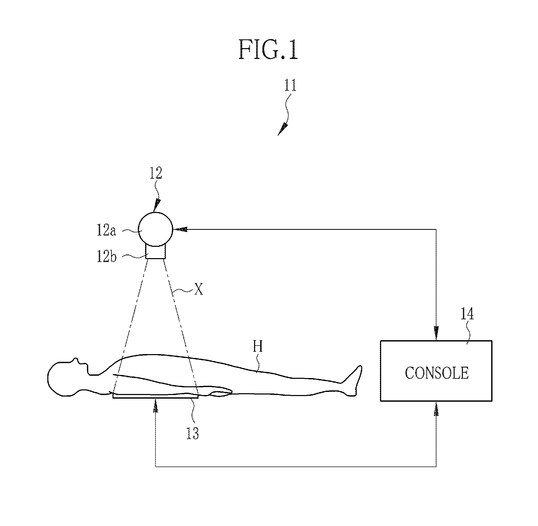
[0042]As shown in FIG. 1, a radiography system 11 consists of a radiation generator 12 for irradiating a specimen or patient H with radioactive rays X, e.g. X-rays, a cassette 13 for detecting X-rays X penetrating the patient H, and a console 14 for controlling the 12 and the cassette 13. The 12 and the cassette 13 are installed in a radiography chamber, whereas the 14 is installed in a control chamber adjacent to the radiography chamber.
[0043]The 12 is constituted of an X-ray tube 12a for generating X-rays X, and a collimator 12b for confining X-rays X from the 12a to a limited irradiation range. The 12 is held on a not-shown carriage device in a movable manner. For example, the 12 may be moved by the carriage device to a position opposing to the cassette 13, so that the X-ray irradiation range may change according to a designated portion or site of the specimen H that may be designated through the 14.
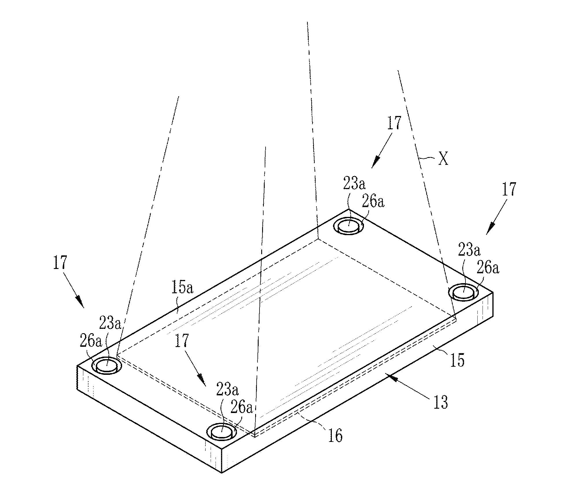
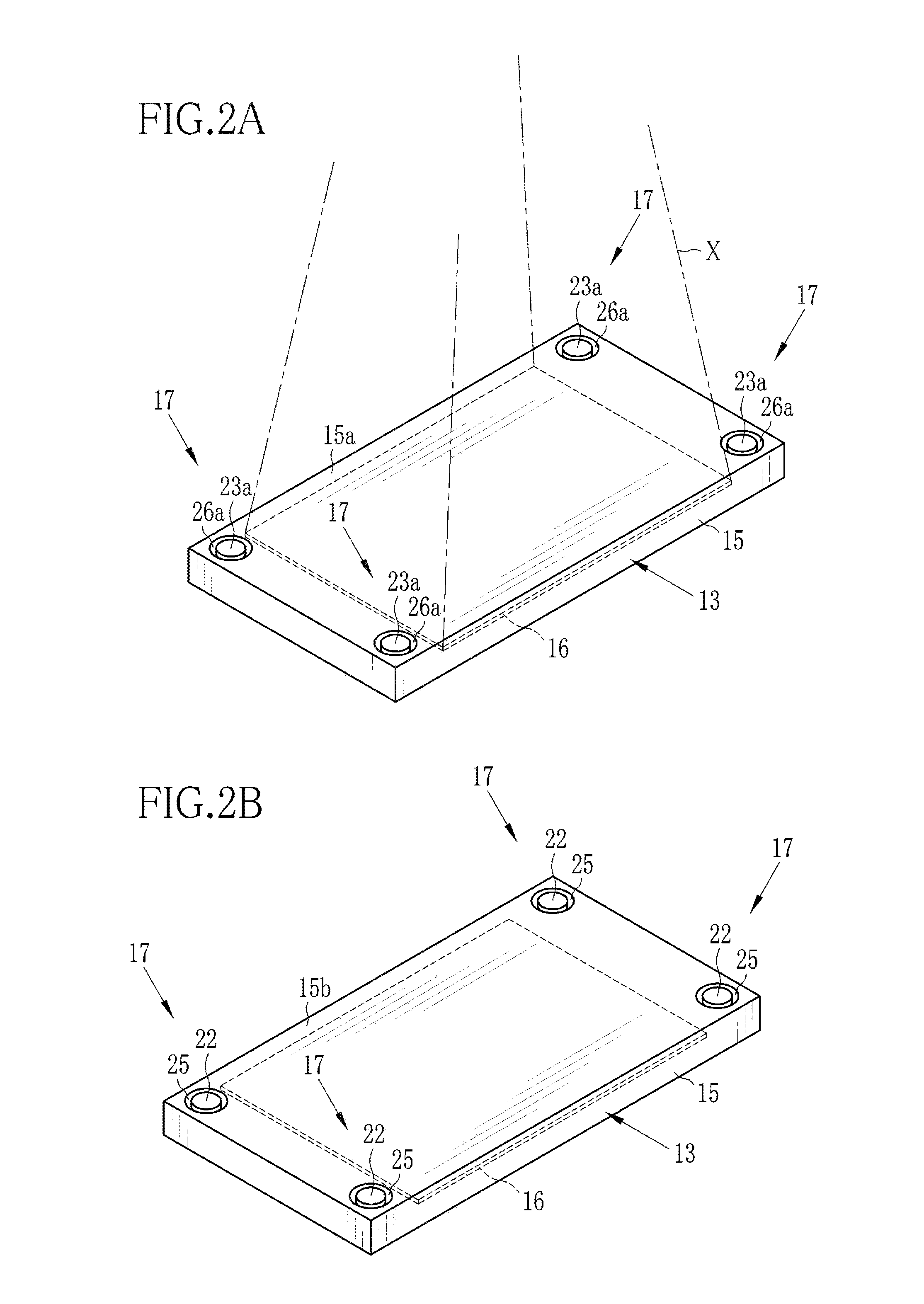
[0044]The cassette 13 generally has an outer size that ca...
second embodiment
[0056][Second Embodiment]
[0057]Referring now to FIG. 6, a radiographic cassette 13 in accordance with a second embodiment will be described. In the second embodiment, the cassette 13 has slip-property changing mechanisms 37 in place of the above-described slip-property changing mechanisms 17. Each of the slip-property changing mechanisms 37 consists of a foot 21, a rubber 22 attached to a bottom face of the foot 21, a push button 23 attached to a top face of the foot 21, and a positioning mechanism 38. Like the first embodiment, the foot 21 is mounted movable between a retracted position located totally within a housing 15 and a protruded position where the bottom face protrudes outward from a bottom side 15b of the housing 15.
[0058]It is to be noted that those components which are substantially equivalent to those described with respect to the first embodiment are designated by the same reference numerals as in the first embodiment, and the description of these components will be o...
third embodiment
[0065][Third Embodiment]
[0066]As shown in FIG. 8, in a third embodiment, a radiographic cassette 13 is provided with slip-property changing mechanisms 47 in place of the slip-property changing mechanisms 17 of the first embodiment. Each of the slip-property changing mechanisms 47 consists of a foot 48, a rubber 22, a push button 23, an interconnection member 49 interconnecting the pushbutton 23 with the foot 48, and a positioning mechanism 50 for positioning the foot 48.
[0067]The respective feet 48 of the slip-property changing mechanisms 47 may protrude through openings 25, which are formed in four corners of a rectangular bottom side 15b of a housing 15. Openings for exposing the push buttons 23 are formed through opposite side surfaces of the housing 15 in both ends of each side surface. Each opening 51 has a recess 51a like the recess 26a of the opening 26 in the first embodiment, and the recess 51a preferably has an external diameter D of 10 mm to 30 mm, for the same reason as ...
PUM
 Abstract
Description
Claims
Application Information