Quick connect mounting system for a ceiling fan

a technology for mounting systems and ceiling fans, which is applied in the direction of casings/cabinets/drawers, casings/cabinets/drawers details, electric devices, etc., can solve the problems of affecting the installation of ceiling fans, affecting the service life of ceiling fans, and requiring repair or replacement. , to achieve the effect of easy wiring the ceiling fan assembly to the electrical wires within the ceiling, and avoiding twisted wire breakage or damag

Inactive Publication Date: 2005-04-14
HUNTER FAN
View PDF18 Cites 44 Cited by
  • Summary
  • Abstract
  • Description
  • Claims
  • Application Information

AI Technical Summary

Problems solved by technology

Notwithstanding the widespread use of ceiling fans, the installation of ceiling fans remains problematic.
Twisted wires are apt to break or be damaged and will require repair or replacement.
Additionally, the rotation of the ceiling fan assembly during installation makes wiring the ceiling fan assembly to the electrical wires within the ceiling more difficult.
With both bracket mounting systems and conventional canopy mounting systems, additional installation problems are common.
For instance, these systems permit the installer only limited physical access through the small slotted opening to wire the ceiling fan assembly to the electrical wires in the ceiling.
Furthermore, the bracket and canopy obstructs the installer's visual inspection of the wiring beyond the small slotted canopy opening.
With limited physical and visual access to the wiring within the bracket or canopy, there is a noticeable increase in the difficulty of installing the ceiling fan assembly, in the time required for installation, in the possibility that wires will become damaged or broken during installation, and in the probability that the wiring connection will be faulty.

Method used


Image

  • Quick connect mounting system for a ceiling fan
  • Quick connect mounting system for a ceiling fan
  • Quick connect mounting system for a ceiling fan

Examples


Embodiment Construction

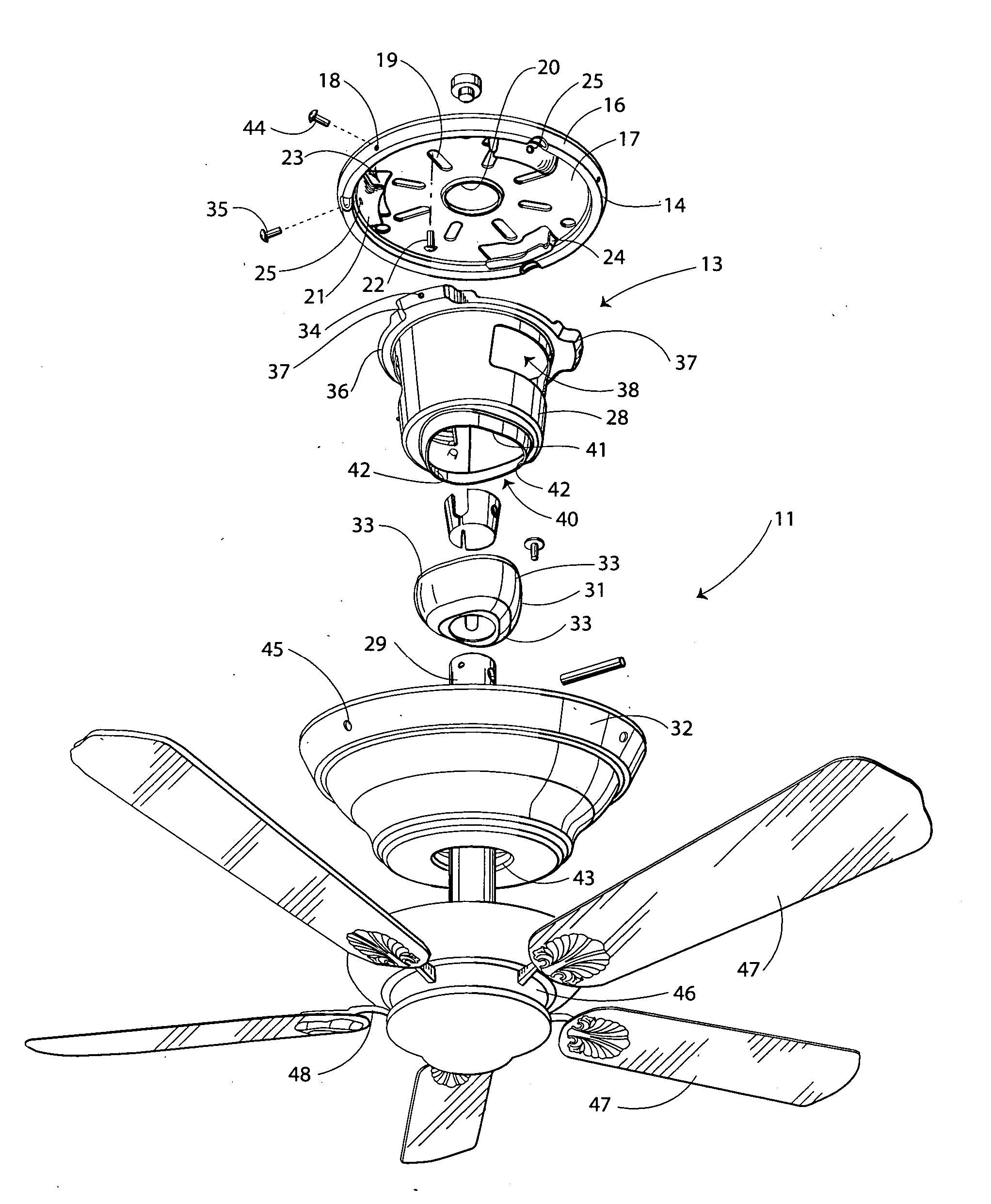
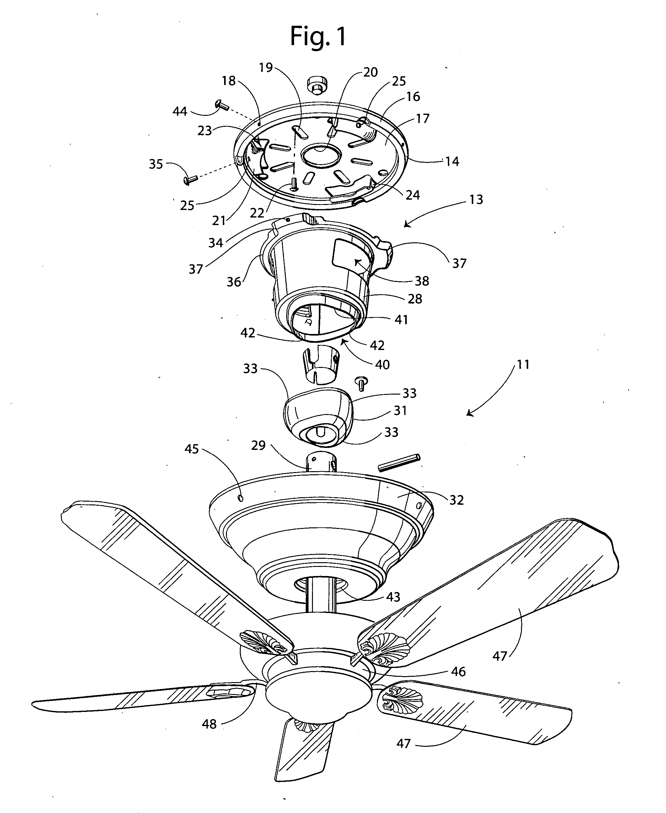
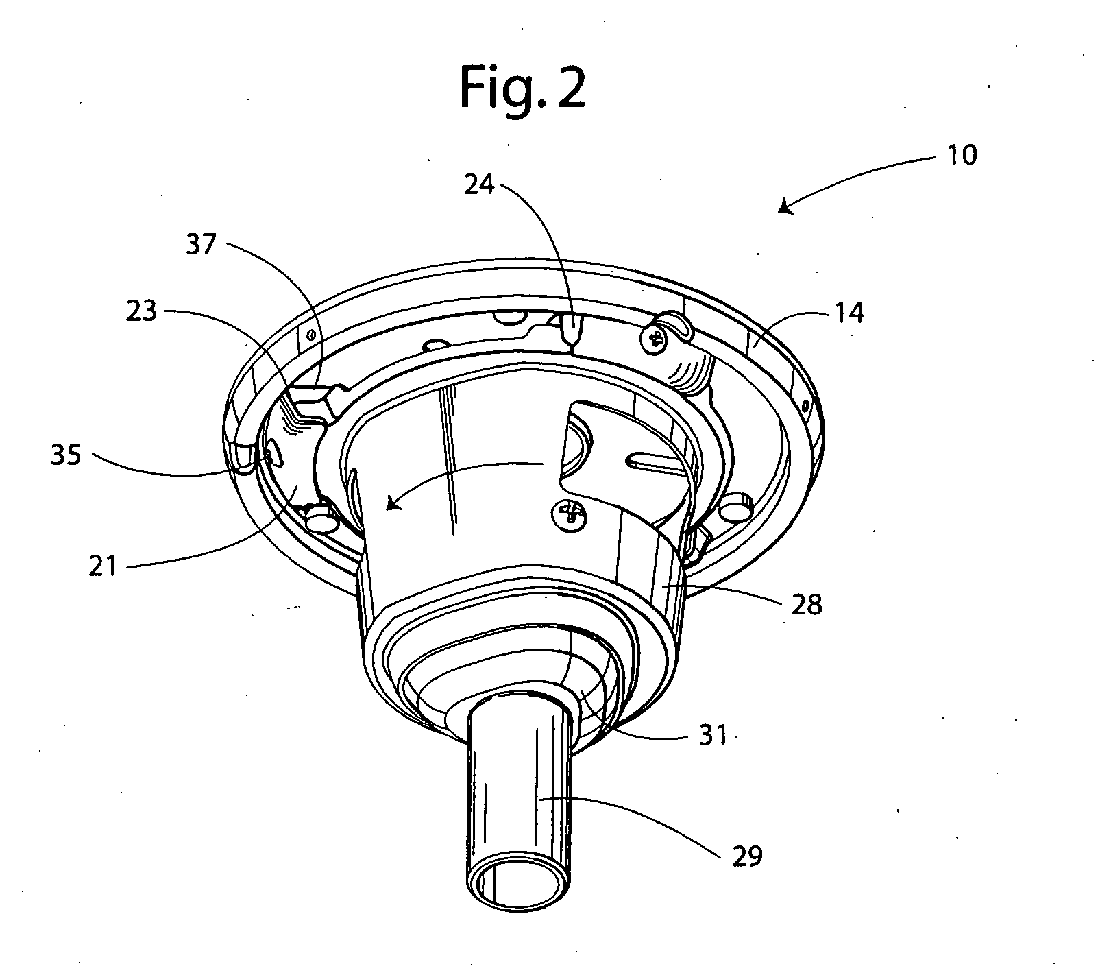
[0013] With reference next to the drawings, there is shown a mounting system 10 and conventional ceiling fan assembly 11 in a preferred form of the invention, shown with the mounting system 10 in an enlarged scale for clarity of explanation. The mounting system 10 includes a mounting plate 14 and a lower hanging assembly 13.

[0014] The mounting plate 14 has a peripheral, annular flange 16 extending from a generally planar central portion 17. The annular flange 16 has an annular array of three mounting holes 18. The central portion 17 has an annular array of mounting holes 19 therein through which two mounting screws 22 are passed and threaded into a supporting surface such as a ceiling C through a conventional junction box, a central wire opening 20, and three tab locks 21. Each tab lock 21 has an open end 23, a closed end 24 and a screw hole 25.

[0015] The lower hanging assembly 13 includes a cup-shaped mounting bracket 28, a downrod 29 coupled to a balljoint 31, and a canopy 32 jo...


PUM


Abstract

A mounting system (10) for supporting a ceiling fan assembly (11) of the type having a motor, motor housing (46), a plurality of blades (47) and a downrod (29) to a ceiling C. The mounting system includes a mounting plate (14) having a plurality of tab locks (21), a mounting bracket having a plurality of locking tabs (37) configured to mate with the tab locks (21). The mounting bracket also has an opening (40) therein configured to receive a ball joint (31) of the downrod (29).

Description

TECHNICAL FIELD [0001] This invention relates to a mounting system for supporting a ceiling fan assembly. BACKGROUND OF THE INVENTION [0002] Ceiling fans have become an increasingly popular supplementary means of creating an airflow within both commercial and residential buildings. Notwithstanding the widespread use of ceiling fans, the installation of ceiling fans remains problematic. [0003] With conventional mounting systems, the weight of the ceiling fan assembly, which includes the ceiling fan motor, motor housing, downrod, blades and blade irons, is supported by either a mounting bracket or a canopy. These mounting brackets or canopies typically include slotted openings extending from their outer edges to their centers, which are adapted to accept and retain the top end of the downrod which commonly ends in a ball joint. [0004] When a bracket mounting system is used, the slotted mounting bracket is mounted either directly or indirectly to the ceiling at the mounting location of...

Claims


Application Information

Patent Timeline
Patent Type & Authority Applications(United States)
IPC IPC(8): F04D25/08F04D29/60
CPCF04D29/601F04D25/088
Inventor BACON, TEDPEARCE, RICHARD A.
Owner HUNTER FAN
Why Eureka
Try Eureka