Image processing device

a processing device and image technology, applied in the field of image processing devices, can solve the problems of increasing the operation speed of the entire output system, affecting so as to improve the quality of dynamic images and the effect of simple circuit configuration and low cos

Inactive Publication Date: 2005-04-14
CANON KK
View PDF17 Cites 32 Cited by
  • Summary
  • Abstract
  • Description
  • Claims
  • Application Information

AI Technical Summary

Benefits of technology

[0061] Therefore it is a first object of the present invention to provide an image processing device which has an inexpensive and simple circuit configuration with qualities of dynamic images improved, and additionally for a plurality of input signal sources, to provide a image processing device which can perform appropriate processing flexibly for dynamic image qualities.

Problems solved by technology

In this frame rate conversion, however, there is a problem of an image quality deterioration of dynamic images as shown in a specific example in FIG. 8.
In this double buffering method, however, the following problem on dynamic images as described below.
If an input signal source has a low frequency such as 50 Hz, however, there is a problem on image qualities since the frequency is further reduced to a half in the same polarity for a device which displays a screen with an inverted polarity for each field like a liquid crystal display and therefore a screen rewrite cycle time is elongated, thereby causing a flickering phenomenon in which an entire view of the screen flickers.
2.6 times as high as a speed of an input when the number of the pixels in VGA is converted to one in XGA for the output, by which there is such a problem that an operation speed of the entire output system must be increased.
To solve this problem, a circuit configuration needs to be modified by adopting components having high operation speeds, developing new components, or dividing an operation system to reduce the speed, which leads to an increase of a cost or an expansion of a circuit scale.
In addition to the above problems, there are problems caused by two or more input systems.
This problem becomes serious for a use of multi-screen in which respective dynamic image qualities are important in further increased input systems.
Furthermore, for a plurality of image inputs, there occurs such a problem that a color, a brightness, a contrast or the like can be optimized so as to be suitable only for a single input system which is characteristic of a multi-screen in various image quality characteristics or that an optimization requires an increase of a circuit scale, in the same manner as for the image qualities of dynamic images.
Providing correction characteristics for image signals in both of the input system and the output system in this manner, however, leads to a need for preparing a plurality of similar circuits, thereby causing an enlargement of a circuit scale and an increase of the number of adjustment items which may cause an increase of a cost.
It is a problem particularly in a configuration having a lot of inputs.
In this case, gray-scale level of the black level of an output image is deteriorated, thereby causing a degradation of an image quality such as a pseudo-outline in the image.
Although there is a method of increasing an operational bit count to prevent this phenomenon, it causes an increase of a cost or an enlargement of a processing system.
As described above, there has been conventionally a problem of an increase of a cost due to an enlargement of a scale in a configuration in which characteristics of different input images are converted to the same display characteristics for a change of characteristics of a display unit in a multi-screen display in which images from a plurality of input signal sources are displayed in the same display unit.
In addition, a circuit has a serious bit error in the circuit configuration, which leads to a problem of a degradation of an image quality.
Therefore, a brightness, a contrast, gray-scale level, colors or the like cannot be easily unified among respective input systems.
If an AGC circuit is included in the input image processing device, a dynamic range of signals can be assured, but signals are automatically corrected and therefore signal levels which should be displayed originally are also corrected, which causes a problem that an intention of a signal transmission side is ignored.

Method used


Image

  • Image processing device
  • Image processing device
  • Image processing device

Examples


first embodiment

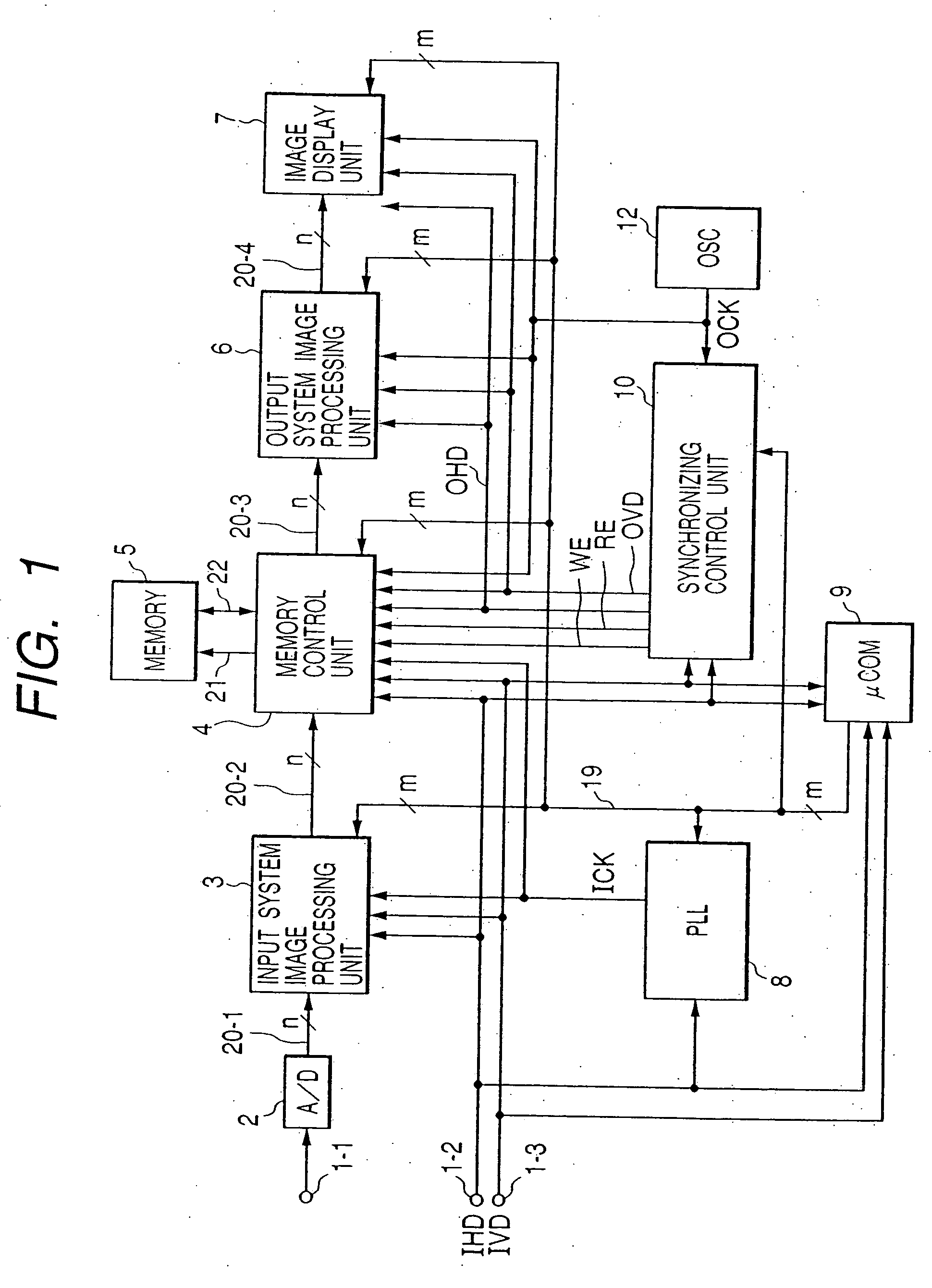
[0103] (First Embodiment)

[0104] Referring to FIG. 1, there is shown a block diagram of assistance in explaining a first embodiment of the present invention. In FIG. 1, reference numerals 1-1, 1-2, and 1-3 designate an input terminal for analog image signals, an input horizontal synchronizing signal (IHD) input terminal, and an input vertical synchronizing signal (IVD) input terminal, respectively. An AD converter 2 converts an entered analog image signal to an n-bit digital signal. There are also shown an input system image processing unit 3, a memory control unit 4, a memory unit 5 for storing image data, an output system image processing unit 6, and an image display unit 7. Reference numerals 20-1, 20-2, 20-3, and 20-4 designate data buses for transmitting n-bit digital signals to respective units. Reference numerals 21 and 22 designate a control bus made of a memory control lines and address lines and memory data bus, respectively.

[0105] There are also shown a PLL circuit 8, a c...

second embodiment

[0130] (Second Embodiment)

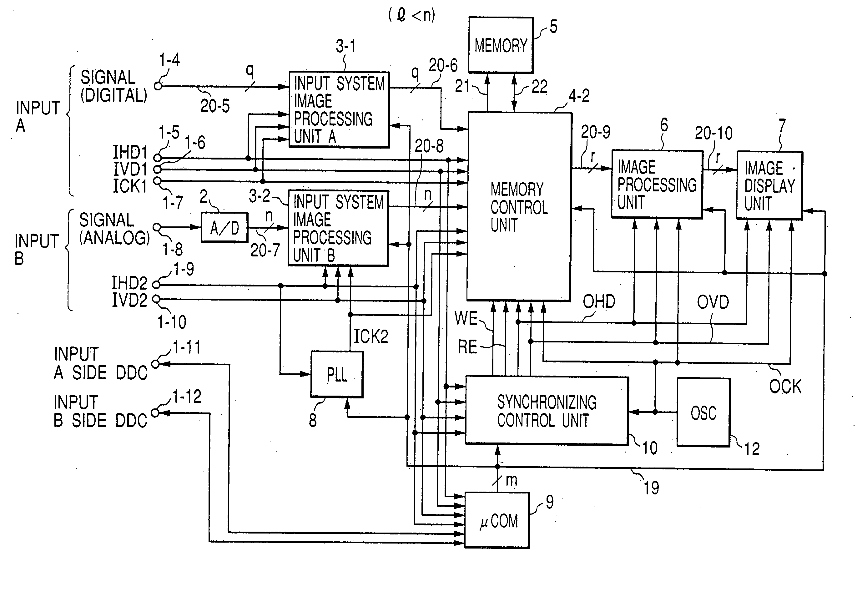
[0131] While there has been described an example of switching whether or not an output system V synchronizing signal is synchronized with an input synchronizing signal according to a vertical frequency of an input in the first embodiment, there is shown an example of switching whether or not it is synchronized with the input synchronizing signal according to an operation purpose or a use in a second embodiment. A block diagram of the second embodiment is shown in FIG. 4.

[0132] In this embodiment, there are two input systems and they are synthesized in a memory control unit. In this circuit configuration a synthetic screen from different input sources is assumed such as, for example, an output screen of the PC displaying a graph or a table over the entire screen (C1) with a dynamic image of a TV phone or the like in a subscreen portion (C2) as shown in FIG. 5. In this condition, signals of both screens generally do not have any synchronous relationship. Add...

third embodiment

[0144] (Third Embodiment)

[0145] Referring to FIG. 21, there is shown a block diagram of an image processing unit for an image display for displaying a multi-screen having two screens in an image display unit of one system with a synthesization by controlling outputs from frame memories, having PC inputs of two systems; digital computer image signal inputs of one system and analog computer image signal inputs of the other system, as a third embodiment of a display to which the present invention is applied.

[0146] In this diagram, there is shown an input terminal 1-1a for q-bit digital computer image signals (IDATA1) of the first system. While there must be three systems of red, blue, and green (RGB) intrinsically, the configuration is described here with one system for simplification of the description (the same shall apply hereinafter). There are shown an input terminal 1-1b for input horizontal synchronizing signals (IHD1), an input terminal 1-1c for input vertical synchronizing si...


PUM


Abstract

An inexpensive and simple circuit for improving the quality of a dynamic image, with appropriate, flexible dynamic image qualities processing, even with plural input signal sources. A memory unit has a region for storing images of at least one screen, and a memory control unit for writing image data to the memory unit on the basis of a first clock and a first image synchronizing signal and for outputting image data read out from the memory unit on the basis of a second clock and a second image synchronizing signal. A clock generating unit provides the second clock, and a synchronizing control unit inputs the second clock and outputs the second image synchronizing signal. The synchronizing control unit generates one signal asynchronous to the first image synchronizing signal, by dividing the second clock, and another that is and synchronized with the first synchronizing signal, by using the second clock, and selects one of the signals it has produced to be output as the second image synchronizing signal. In a case of multiple input signals, then such fourth image synchronizing signals equal in number to the input signals are produced.

Description

BACKGROUND OF THE INVENTION [0001] 1. Field of the Invention [0002] The present invention relates to an image processing device for converting image signals having various formats to image signals in a desired format or for synthesizing the image signals. [0003] 2. Related Background Art [0004] The development of multimedia in recent years provides occasions in which images in various image signal formats are displayed on a display screen. Particularly, while a display of a TV set had once been quite different from that of a personal computer (PC), a TV capable of displaying PC images and a PC display to which TV signals can be entered have appeared due to an advancement of their unification. In addition, due to an appearance of video sources in new digital formats such as a digital television or MPEG or due to an advancement of three-dimensional graphics, motion picture is more frequently displayed also on PC displays. [0005]FIG. 6 shows a block diagram of the conventional display....

Claims


Application Information

Patent Timeline
Patent Type & Authority Applications(United States)
IPC IPC(8): G09G3/36G09G3/291G09G3/296G09G5/00H04L12/40H04L12/64H04N5/20H04N5/202H04N5/45H04N5/66
CPCH04L12/40117H04N5/45H04N5/20H04N21/4305H04N21/4316H04N21/43632
Inventor SHIGETA, KAZUYUKI
Owner CANON KK
Why Eureka
Try Eureka