

Control device of exhaust recirculation valve
a control device and valve technology, applied in the direction of valve operating means/releasing devices, machines/engines, mechanical equipment, etc., can solve the problems of low reliability, difficult optimum control, limited open-loop control response characteristic of stepping motor m, etc., and achieve the effect of simple configuration and negative hysteresis generating circui
- Summary
- Abstract
- Description
- Claims
- Application Information
AI Technical Summary
Benefits of technology
Problems solved by technology
Method used
Image

Examples
first embodiment
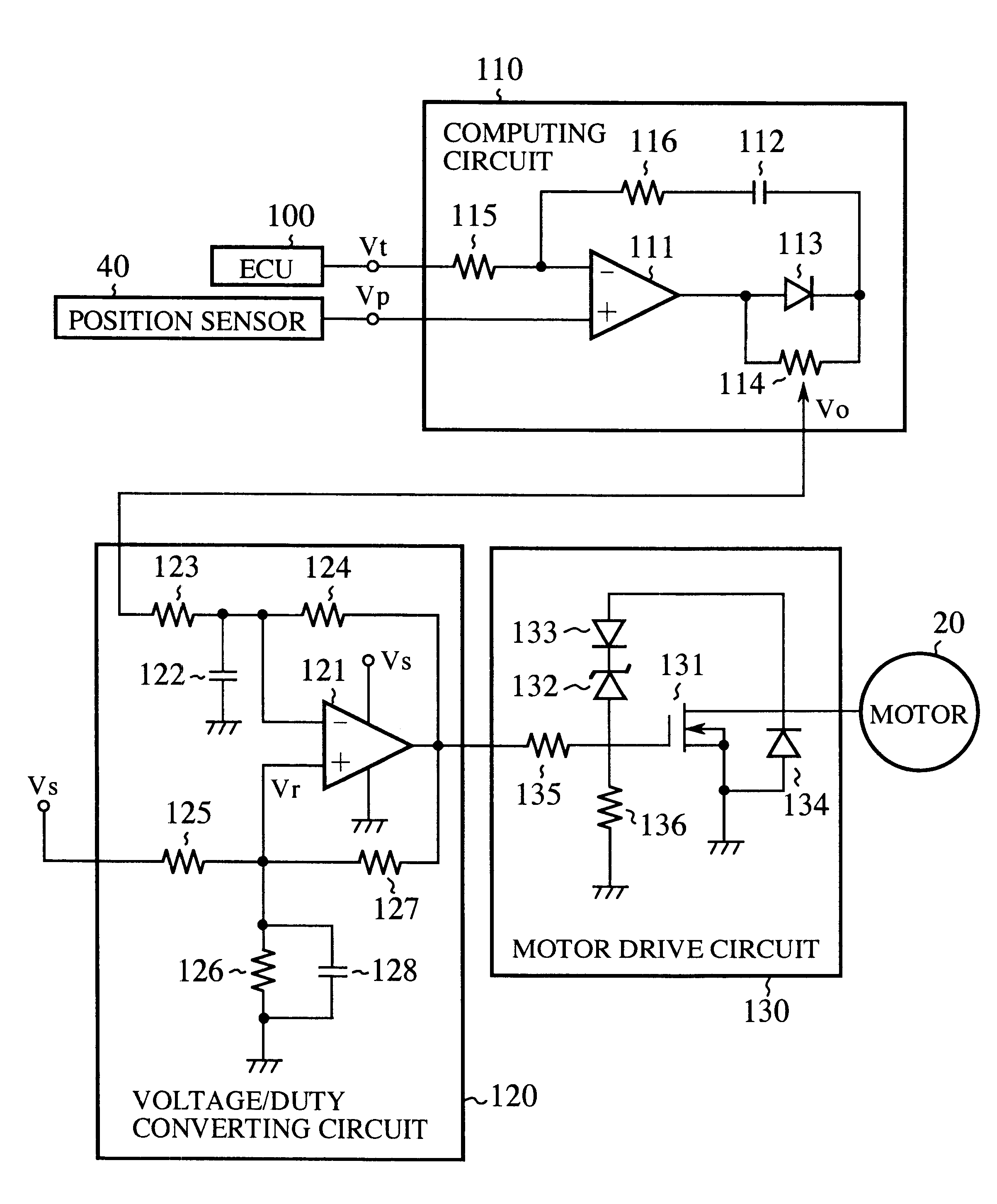
FIG. 6 is a circuit diagram showing a control apparatus for controlling an EGR valve according to the first embodiment.
Referring to FIG. 6, reference numeral 110 denotes a computing circuit which receives a target value signal indicative of the degree of a valve opening given by an external ECU 100, and a current-position signal of the valve from a position sensor 40 inside the EGR valve. The control apparatus comprises a comparator 111, a capacitor 112, a diode 113, a variable resistor 114, and resistors 115, 116. Reference numeral 120 denotes a voltage-duty converting circuit for changing the duty of the output signal based on a control signal from the computing circuit 110, and which comprises an operational amplifier 121, capacitors 122, 128, and resistors 123 to 127. Reference numeral 130 denotes a motor driving circuit for driving the DC motor 20 by the output signal of the voltage-duty converting circuit 120, and which comprises a switching element 131, a Zener diode 132, dio...
second embodiment
FIG. 8 is a circuit diagram having built a negative hysteresis generating circuit into a computing circuit in the control apparatus according to a second embodiment.
Instead of the diode 113 and the resistor 114 on the output side of the comparator 111 in the computing circuit 110 in FIG. 6 of the above first embodiment, a Zener diode 117 is provided as a negative hysteresis generating circuit.
The operation of the second embodiment will now be described.
(a) Vt>Vp
In this case, the current flows through the circuit in the direction of a solid-line arrow. At this time, since the voltage to be generated in the Zener diode 117 becomes "0", thus
Vo-hys=Vo
(b) Vt
In this case, the current flows through the circuit in the direction of a dotted-line arrow. At this time, since the voltage to be generated in the Zener diode 117 becomes "Vz", thus
Vo-hys=Vo+Vz
As a result, it is possible to generate the negative hysteresis characteristics.
As the circuit for generating the negative hysteresis, any ...
PUM
 Abstract
Description
Claims
Application Information