Device for testing lsi to be measured, jitter analyzer, and phase difference detector

a technology of jitter analyzer and detector, which is applied in the direction of noise figure or signal-to-noise ratio measurement, instruments, pulse technique, etc., can solve the problems of not getting the correct test result, the value of even the same output data acquired at the fixed timing of the strobe is not constant, and the difficulty of correct test or judgmen

Inactive Publication Date: 2005-04-14
ADVANTEST CORP
View PDF11 Cites 28 Cited by
  • Summary
  • Abstract
  • Description
  • Claims
  • Application Information

AI Technical Summary

Problems solved by technology

However, since the output data of the LSI to be measured has a jitter (irregular fluctuation of the timing), the value of even the same output data acquired at the fixed timing of the strobe is not constant, and a problem has occurred that a correct test result is not obtained.
Therefore, in the conventional test equipment which acquires the output data by the fixed strobe, the data which is originally the same fluctuates by an influence of jitter, and a problem has occurred that correct test or judgment is difficult.
However, in the conventional jitter analysis using a jitter measurement unit, there is a possibility that an error is generated in the operation of the oscilloscope or the like.
It is difficult to analyze the jitter with high precision.
Moreover, an operation of acquiring and measuring a large number of data is complicated, and a problem that the jitter analysis requires much time and labor has been pointed out.
Especially in the speeded-up LSI, such difficulty in the jitter analysis has been remarkable.

Method used


Image

  • Device for testing lsi to be measured, jitter analyzer, and phase difference detector
  • Device for testing lsi to be measured, jitter analyzer, and phase difference detector
  • Device for testing lsi to be measured, jitter analyzer, and phase difference detector

Examples


first embodiment

[First Embodiment]

A first embodiment of the phase difference detector for the LSI to be measured according to the present invention will be described hereinafter with reference to FIGS. 7 and 8.

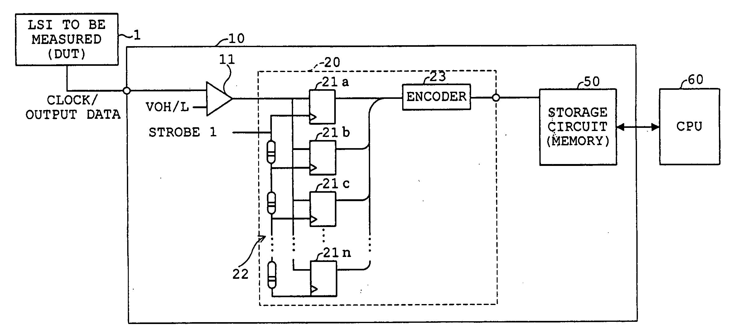
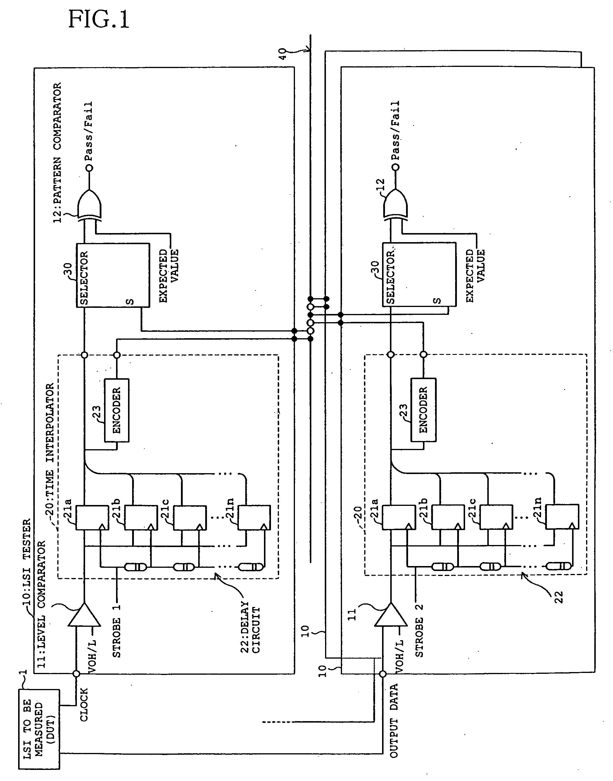
FIG. 7 is a block diagram showing a constitution of the first embodiment of the phase difference detector for the LSI to be measured according to the present invention. As shown in FIG. 7, the phase difference detector for the LSI to be measured according to the present embodiment has a constitution substantially similar to that of the LSI tester 10 in the test equipment for the LSI to be measured shown in FIG. 1. Additionally, the phase difference detector of the present embodiment comprises a subtraction circuit 90 and decoder 70 instead of the selector 30 and pattern comparator 12 of the LSI tester 10 in FIG. 1.

The other constitution is similar to that of the LSI tester 10 shown in FIG. 1.

As shown in FIG. 7, the LSI tester 10 disposed in the phase difference detector of the present e...

second embodiment

[Second Embodiment]

Next, a second embodiment of the phase difference detector for the LSI to be measured according to the present invention will be described with reference to FIG. 9.

FIG. 9 is a block diagram showing a constitution of the second embodiment of the phase difference detector for the LSI to be measured according to the present invention. As shown in FIG. 9, the phase difference detector for the LSI to be measured according to the present embodiment further comprises a plurality of counters 80a to 80n to count the output signals of the decoder 70 for each output terminal in the phase difference detector shown in FIG. 7, and is constituted to acquire a distribution of phase differences between the clock and output data of the LSI to be measured 1 from a plurality of data output from the counters 80a to 80n.

When the phase difference between the clock and output data output from the LSI to be measured 1 is acquired, the output result of the subtraction circuit 90 is dec...


PUM


Abstract

An LSI test equipment can acquire output data of an LSI as a device under test by a clock signal output from the LSI to be measured and acquire measurement data synchronously with the output data having jitter. The LSI test equipment (10) includes a clock side time interpolator (20) for acquiring the clock output from the LSI (1) to be measured by a plurality of strobes having a predetermined timing interval and outputting it as encoded level data of time series, a data side time interpolator (20) for acquiring the output data output from the LSI (1) to be measured by a plurality of strobes having a predetermined timing interval and outputting it as level data of time series, and a selector (30) for receiving the level data from both of the time interpolators, selecting output data at the clock edge timing, and outputting it as data to be measured.

Description

TECHNICAL FIELD The present invention relates to a test equipment for a function test in which output data output from an LSI as a device under test is compared with predetermined expectation value data to judge whether or not the LSI to be measured is failure, a jitter analyzer for analyzing a jitter of a clock or output data of an LSI to be measured which is a function test object, and a phase difference detector which detects a phase difference between a clock and output data of an LSI to be measured. The present invention relates particularly to a test equipment, in which a source synchronous circuit capable of acquiring a clock and output data output from an LSI to be measured as level data in a time series; in which a clock signal output from the LSI to be measured is accordingly usable as a timing signal to take in the output data of the LSI to be measured; which is capable of taking in the output data at a signal change point synchronized with a jitter; which is capable of...

Claims


Application Information

Patent Timeline
Patent Type & Authority Applications(United States)
IPC IPC(8): G01R29/26G01R31/317G01R31/319G01R31/3193H04L1/20
CPCG01R29/26G01R31/31709H04L1/205G01R31/31937H03K5/135G01R31/31922
Inventor KANTAKE, SHUUSUKE
Owner ADVANTEST CORP
Why Eureka
Try Eureka