Latch with switch

a latch and switch technology, applied in the field of latches, can solve the problems of high cost, high cost, and the cost of latches with switches, and achieve the effects of preventing poor contact, manufacturing inexpensively, and reducing cos

Active Publication Date: 2005-04-21
NIFCO INC
View PDF6 Cites 5 Cited by
  • Summary
  • Abstract
  • Description
  • Claims
  • Application Information

AI Technical Summary

Benefits of technology

[0010] According to the invention, the switch is formed of the movable terminal comprising the pin attached to the movable member and having the both ends protruding from the two opposite side surfaces of the movable member, and the pair of the fixed terminals fixed oppositely inside the housing, and when the movable member is in the protruding position, the both ends of the movable terminal do not contact in the non-conducting state or contact in the conducting state, and when the movable member is in the pushed-in position, the both ends of the movable member contact in the conducting state or do not contact in the non-conducting state. Accordingly, the movable terminal can be manufactured inexpensively, whereby the latch with a switch can be manufactured inexpensively. Also, the movable terminal is always forced by the forcing member toward a direction of protruding from the housing, and contacts the fixed terminals in the forced state. Accordingly, it is possible to prevent poor contact between the movable terminal and the fixed terminals, thereby improving reliability of the switch.
[0011] Also, it is arranged such that the movable terminal is incorporated from the movable terminal insertion through hole provided in the side surface of the housing. Accordingly, the movable terminal becomes easier to assemble, and the assembly operation can be performed with good operating characteristics.
[0012] Also, the movable terminal is capable of rotation relative to the movable member. Accordingly, the movable terminal contacts the pair of the fixed terminals at various parts thereof, thereby improving reliability of the switch.
[0013] Furthermore, the cross-section of the movable terminal is made circular. Accordingly, a state of contact between the fixed terminals and the movable terminal becomes stable, thereby improving reliability of the switch.

Problems solved by technology

Because the movable terminal is manufactured by applying a cutting process and bending process to a thin metal plate, it becomes expensive (cost up).
Accordingly, the latch with a switch becomes expensive.

Method used


Image

  • Latch with switch
  • Latch with switch
  • Latch with switch

Examples


Embodiment Construction

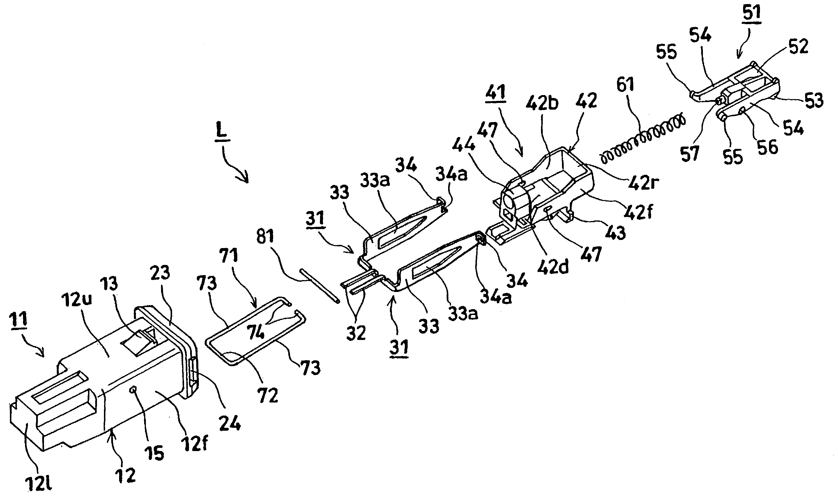
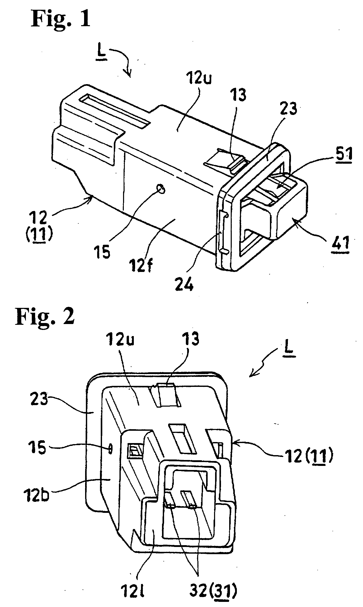
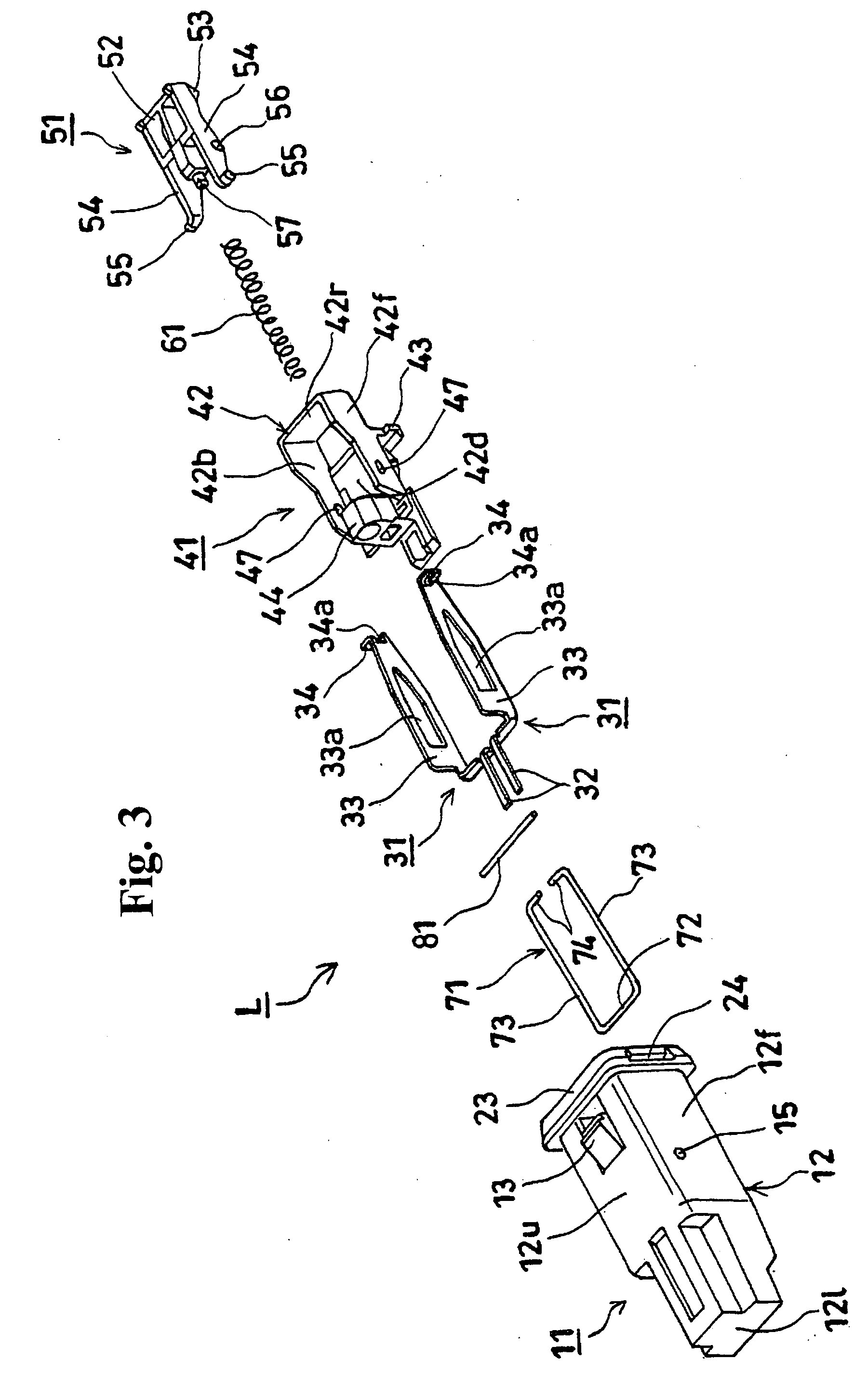
[0044]FIG. 1 is a perspective view seen from a front of a latch with a switch according to a first embodiment of the invention. FIG. 2 is a perspective view seen from a back of the latch with a switch shown in FIG. 1. FIG. 3 is an exploded perspective view of the latch with a switch shown in FIG. 1 and FIG. 2.

[0045] In these drawings, symbol L indicates the latch with a switch. The latch is formed of a box-like housing 11 with one open side surface (right side surface); a pair of fixed terminals 31 fixed inside the housing 11; a movable member 41 inserted into the housing 11; a checking member 51 attached to the movable member 41 to be capable of rotating; a coil spring 61 placed between the checking member 51 and the housing 11 as a forcing member for urging the movable member 41 toward a direction of protruding from the housing 11 via the checking member 51; a guide lever 71 attached to the housing 11; and a pin 81 as a movable terminal with a circular cross-section attached to t...


PUM


Abstract

In a latch with a switch, when a movable member is pushed into a housing against a force of a coil spring, the movable member is locked in a pushed-in position by a lock mechanism and a switch is turned on. When the movable member is pushed again into the housing, the movable member is returned to a protruding position and the switch is turned off. The switch is formed of a pin attached to the movable member and having both ends protruding from two opposite sides of the movable member; and a pair of fixed terminals fixed inside the housing. When the movable member is at the protruding position, both ends of the pin become a conducting state, and when the movable member is at the pushed-in position, both ends of the pin become a non-conducting state. The conducting and non-conducting states can be reversed.

Description

BACKGROUND OF THE INVENTION AND RELATED ART STATEMENT [0001] The invention relates to a latch with a switch, wherein the switch is provided on the latch attached to an attachment receiving member such as a main body, so that an opening and closing member such as a door of a radio cassette player is pushed to close, and the opening and closing member is pushed again to open. [0002] A conventional latch with a switch is constituted such that, by pushing a movable member forced by a forcing member to a position where a part thereof protrudes from a housing into a housing against a force of the forcing member, a push-push type lock mechanism becomes a locked state, and the movable member is locked in a pushed-in position and the switch is turned on; and by pushing the movable member in the pushed-in position into the housing against the force of the forcing member, the lock mechanism becomes an unlocked state, and the movable member is returned to the protruding position by the force of...

Claims


Application Information

Patent Timeline
Patent Type & Authority Applications(United States)
IPC IPC(8): E05C3/24E05B27/00E05C19/02H01H3/42H01H13/56
CPCH01H27/00H01H13/562E05B27/00E05C3/24E05C19/02
Inventor ICHIMARU, TAKAHIDE
Owner NIFCO INC
Why Eureka
Try Eureka