Optical line transmission protection system and method

A technology of optical line transmission and protection system, applied in the field of optical line transmission protection system, can solve the problems of low switching time and inability to solve switching reliability at the same time, achieve the effect of reducing switching time, improving switching reliability, and ensuring smooth business

Active Publication Date: 2011-11-30
HUAWEI TECH CO LTD
View PDF4 Cites 4 Cited by
  • Summary
  • Abstract
  • Description
  • Claims
  • Application Information

AI Technical Summary

Problems solved by technology

[0005] Embodiments of the present invention provide an optical line transmission protection system and method, which are used to solve the defects of low switching reliability and long switching time in the prior art, simplify the handshake process, and achieve improved switching reliability and reduced switching time

Method used


Image

  • Optical line transmission protection system and method
  • Optical line transmission protection system and method
  • Optical line transmission protection system and method

Examples


Embodiment 1

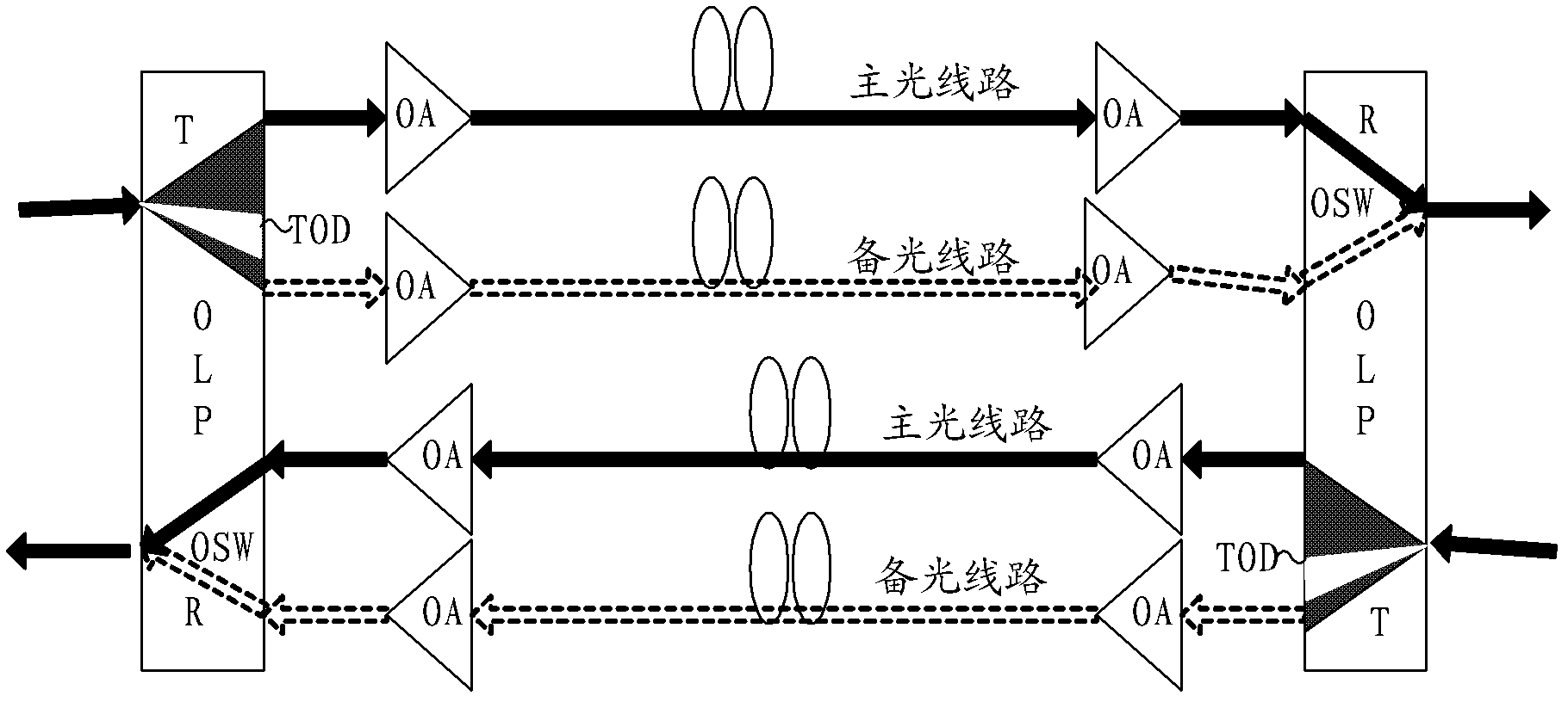
[0025] Figure 1a A schematic structural diagram of an optical line transmission protection system provided in Embodiment 1 of the present invention, as shown in Figure 1a , the optical line transmission protection system may include: at least one level of optical line protection section, the optical line protection section includes: a sending end and a receiving end, and the sending end is provided with an optical power distribution adjustment module (Tunable Optical Divide Module; referred to as : TOD), the receiving end is provided with an optical switch OSW; wherein, the primary optical line protection section is from one OLP to another OLP. An optical line protection section may include one or more spans (for example: between two optical amplification sites OA). The optical power distribution adjustment module TOD can pre-set the optical splitting ratio of the main optical line and the backup optical line on the current working channel according to the difference between ...

Embodiment 2

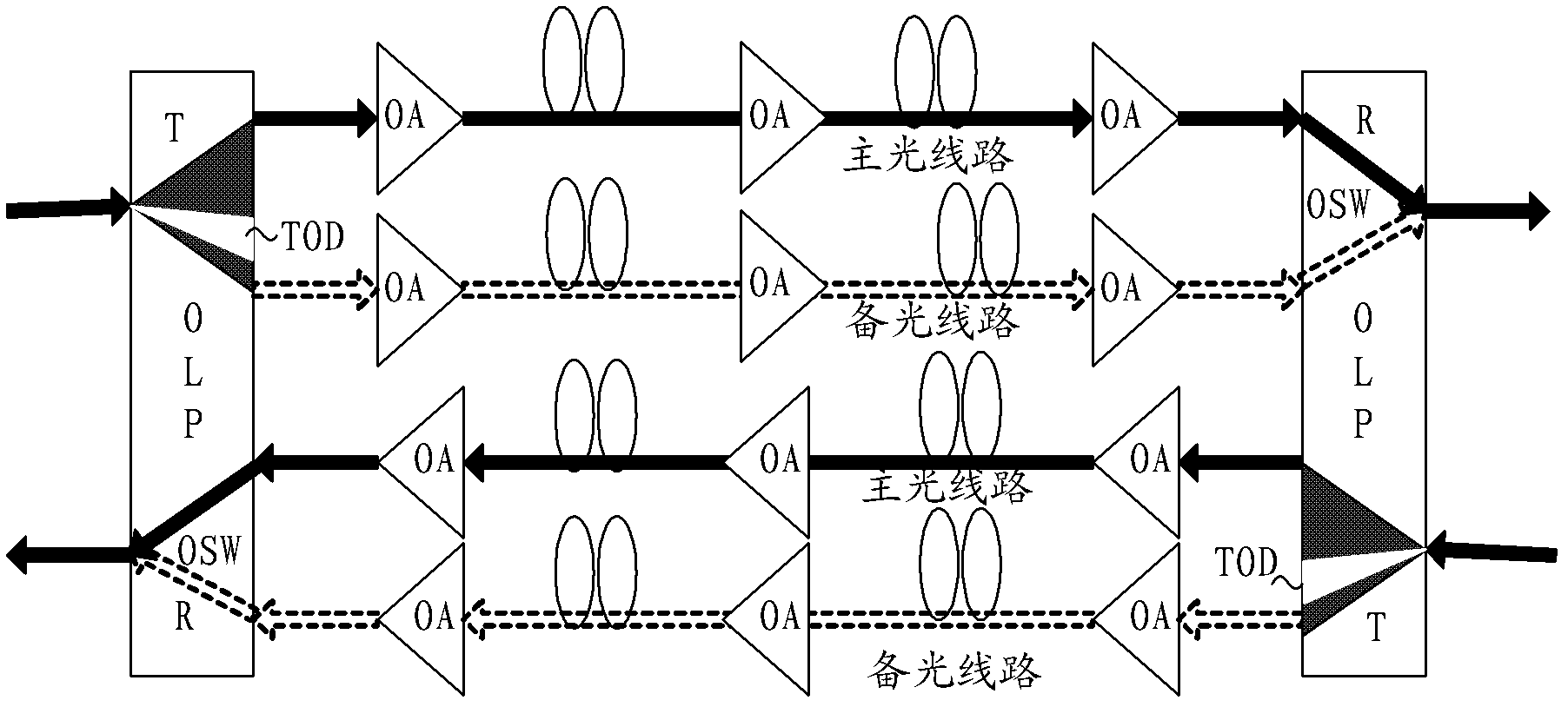
[0033] Figure 2a A schematic structural diagram of the optical line transmission protection system provided in Embodiment 2 of the present invention, as shown in Figure 2a As shown, on the basis of Embodiment 1, the optical power distribution adjustment module may include any one or more of the following units:

[0034] The first splitting ratio setting unit 21 is used to set the splitting ratio of the standby optical line to the minimum splitting ratio of the backup optical line if the current working channel is the main optical line, and set the splitting ratio of the main optical line to the minimum splitting ratio of the standby optical line. Set to "1 minus the minimum splitting ratio of the backup optical line";

[0035] The second splitting ratio setting unit 23 is used to set the splitting ratio of the main optical line to the minimum splitting ratio of the main optical line if the current working channel is a backup optical line, and set the splitting ratio of the ...

Embodiment 3

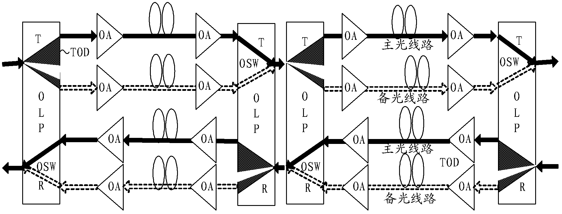
[0046] Figure 3a It is a schematic diagram of an application scenario of the optical line transmission protection method provided by Embodiment 3 of the present invention. When detecting the signal optical power of the OLP of the cascaded system, the upstream OLP is switched to cause the downstream power to change. If there is a detection speed The difference may easily cause false switching of the downstream OLP. In order to solve the misleading problem in the cascaded system, a reference light can be coupled in at the transmitting end of the OLP, and the reference light can be separated at the receiving end of the OLP for optical power detection. The detection of the reference light and the detection of the signal light are carried out simultaneously, and the two signals can be used to simultaneously judge whether the switching condition is satisfied, which can solve the misleading switching in the cascade application. However, since the reference light is an independent s...


PUM


Abstract

The present invention discloses an optical line transmission protection system and method, wherein the optical line transmission protection system comprises at least one grade optical line protection segment comprising a transmitting end and a receiving end. The transmitting end is provided with an optical power distribution adjustment module, the receiving end is provided with an optical switch, the transmitting end of optical line protection at a home terminal and the receiving end of the optical line protection at an opposite terminal are connected to form a main optical line and a preparative optical line, the optical power distribution adjustment module is used for setting the splitting ratio of the main optical line and the preparative optical line according to the optical fiber state difference of the current working channel and nonworking channel, and the optical power distribution of the transmitting end corresponding to the main optical line and the preparative optical line can be adjusted according to the splitting ratio of the main optical line and the preparative optical line. The embodiments of the present invention enable the handshaking process to be simplified, the switching reliability to be increased and the switching time to be reduced.

Description

technical field [0001] The embodiments of the present invention relate to the technical field of communications, and in particular to an optical line transmission protection system and method. Background technique [0002] In 1+1 line protection, in single-span or multi-span scenarios from Optical Terminal Multiplexer (OTM) to OTM, the optical line protector (Optical Line Protector; OLP) sender uses The 50:50 coupler splits the signal light equally and sends it to the main and backup lines, and the receiving end of the OLP uses an optical switch for selective reception. In the application scenario of OTM to OTM single-span or multi-span transmission, since the transmitting end uses a 50:50 coupler, the optical transmission line system introduces an additional loss of about 3dB; if the transmission distance of the optical transmission line exceeds a certain value, the 3dB The loss has a great impact on the performance of the optical transmission line system (optical power bu...

Claims


Application Information

Patent Timeline
Patent Type & Authority Applications(China)
IPC IPC(8): H04Q11/00H04B10/08H04B10/12H04B10/032
CPCH04Q2011/0081H04Q11/00H04B10/032H04J14/0291H04Q2213/1301
Inventor 王红启李时星罗军张德江
Owner HUAWEI TECH CO LTD
Why Eureka
Try Eureka