Dimmable filter

A filter and dimming technology, which is applied in the direction of light guide, optics, instrument, etc., can solve the problems such as the steepness of the waveform edge and the flatness of the top, the reduction of adjacent channel isolation, and no implementation plan, etc., to achieve a compact structure , low cost and easy operation

Inactive Publication Date: 2013-04-03
FUZHOU PHOTOP QPTICS CO LTD
View PDF6 Cites 15 Cited by
  • Summary
  • Abstract
  • Description
  • Claims
  • Application Information

AI Technical Summary

Problems solved by technology

The spectrally tunable filter disclosed in this patent, such as figure 1 As shown, it includes a fiber collimator 101, a beam expander system 102, a grating element 103, a 4f system 104, 105 and a micro-electromechanical system 106 (MEMS, Micro-electromechanical Systems). If the angle changes, the filtering effect can be achieved, but the edge steepness and top flatness of the filtered waveform are not good enough.
The US patent "Compact High-Resolution Tunable Optical Filter Using Optical Diffraction Element And a Mirror" (Compact High-Resolution Tunable Optical Filter Using Optical Diffraction Element And a Mirror, NO.US 2008 / 0085119 A1) mentions the use of The method of a single grating, but there is no specific implementation, and it is believed that the optical performance of such a system is low, such as reducing the adjacent channel isolation, etc.

Method used


Image

  • Dimmable filter
  • Dimmable filter
  • Dimmable filter

Examples


Embodiment 1

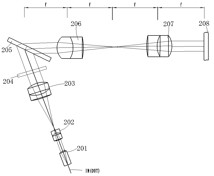
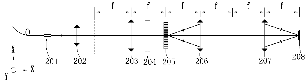
[0039] Embodiment one, such as Figure 2-4 As shown, among them, image 3 and 4 They are schematic diagrams of the optical paths of the X-Z plane and Y-Z plane of the filter, the filter includes a fiber collimator 201, a beam expander system 202, 203 composed of two lens groups, an etalon 204, a diffraction grating 205, a 4f system 206, 207, and a micro-motor system 208 , as shown in the figure, the micro-electromechanical system 208 is located at the focal plane of the 4f system 206, 207, wherein the fiber collimator 201 can use two single-fiber collimators or a double-fiber collimator, considering cost and structural issues, In the present invention, a double-fiber collimator is preferred to realize the input and output of light. One optical fiber (IN) on the collimator is used as the input port of the signal light, and the other optical fiber (OUT) is used as the output port of the signal light; the etalon used 204 is a transmission etalon, which can be an adjustable sing...

Embodiment 2

[0040] In the second embodiment, the "flat-top" effect of the waveform filtered by the transmission single-cavity etalon is not obvious, while the reflective single-cavity etalon can in principle obtain better "steep" and "flat-top" effects, so consider Utilizing the reflective properties of the etalon, a single reflective single-cavity etalon is used to replace the transmissive etalon in Embodiment 1, which is placed behind the MEMS. Such as Figure 5 , the distance between the MEMS 308 and the 4f system 306, 307 is reduced, and the mirror of the MEMS 308 is used to reflect the signal light to the virtual focal plane of the 4f system 306, 307, and the etalon 304 is set on the virtual focal plane, and the Reflective properties reflect the light, and reflect it back to the 4f system 306, 307 through the mirror of the micro-electromechanical system 308, and then it is coupled to the output port of the fiber collimator 301 after passing through the diffraction grating 305 and the...

Embodiment 3

[0041] Embodiment 3, when using a reflective single-cavity etalon, the etalon can also be directly embedded on the mirror of the MEMS, such as Figure 8-10 shown, where Figure 9 and Figure 10 It is a schematic diagram of the optical path of this embodiment on the X-Z and Y-Z planes, the etalon 404 is directly arranged on the micro-motor system 408, and is arranged at the focal plane of the 4f system 406, 407, and the reflection characteristic of the etalon 404 is used to reflect the signal light back to the 4f system , and then coupled to the output port of the fiber collimator 401 after passing through the diffraction grating 405 and beam expander systems 402 and 203 . The filter structure of this embodiment is more compact, and the filtering effect is better.


PUM


Abstract

The invention discloses a dimmable filter which comprises an optical fiber collimator, a beam-expanding system, a diffraction grating, a 4f system and a micro-electromechanical system (MEMS) with a reflector, and also comprises an etalon or a slit aperture. The chromatic dispersion action of the diffraction grating is matched with a filter regulation action of the MEMS technology, so that the dimmable filtering performance of the light filter is realized, and the problem of flattening in optical communication is solved by utilizing the etalon and the slit aperture. The signal filtered by the dimmable filter has high edge steepness and top flatness, and the filter has the advantages of low insertion loss, compact structure, low cost and easiness and convenience in operation.

Description

technical field [0001] The invention relates to the field of optics and optical communication, in particular to a grating adjustable optical filter. Background technique [0002] With the continuous development of modern communication services, the bandwidth requirements for optical fiber communication are getting higher and higher. At present, the preferred solution to increase the bandwidth of optical fiber communication is the wavelength division multiplexing system (WDM:Wavelength Division Multiplexing). Its optical channel spacing has been striding forward from 100GHz to 50GHz system, and is developing towards 25GHz system. [0003] The optical filter is a kind of band-pass filter. In WDM, the optical filter can be used for screening of different channels. Traditional optical filters are non-adjustable optical filters, and their filtering performance is aimed at one or several specific channels. In the initial stage of WDM system development, due to the small number ...

Claims


Application Information

Patent Timeline
Patent Type & Authority Applications(China)
IPC IPC(8): G02B6/293G02B27/44
Inventor 林磊张建英张新汉
Owner FUZHOU PHOTOP QPTICS CO LTD
Why Eureka
Try Eureka