Mold clamping unit

a technology of clamping unit and clamping nuts, which is applied in the field of mould clamping units, can solve problems such as noise development, and achieve the effect of reducing the space requirement for the arrangement of spindles, clamping nuts and actuators

Active Publication Date: 2007-05-03
SUMITOMO SHI DEMAG PLASTICS MACHINERY
View PDF6 Cites 4 Cited by
  • Summary
  • Abstract
  • Description
  • Claims
  • Application Information

AI Technical Summary

Benefits of technology

[0008] The present invention resolves prior art problems by providing a threaded engagement of the threaded spindle with two components, namely the clamping nut and the spindle nut, whereby the clamping nut and the spindle nut are braced with one another and with the respective platen in the active state while the actuator is freed from any locking forces. Thus, release and locking of the mold height adjustment can be implemented in accordance with the present invention with an adjustment system which, compared to conventional systems that must be dimensioned powerful enough to cope with the locking forces, can be constructed with much less power output, namely up to six times less power output, so that space requirements and energy need of a mold height adjustment system according to the invention can be significantly reduced. In addition, the platen remains on the threaded spindle without axial play and without thread-to-thread clearance, when the actuator applies the tightening force, even when the stroke changes. Still the mold height adjustment can be changed independently of the stroke position even during a travel of the moving platen.
[0009] According to another feature of the present invention, an operating mechanism may be provided for shifting the actuator to the active position in order to apply the tightening force, with the actuator being constructed to spontaneously return to the idle position, when the operating mechanism is no longer effective. In this way, overall construction is simplified, the switching reliability is enhanced, and the need for elastic biasing or return elements is eliminated.
[0011] According to another feature of the present invention, the threaded spindle may be restrained against rotation, and the spindle nut may be rotatably arranged on the respective one of the platens with axial play, wherein the actuator can be securely fixed to this platen, while the clamping nut is rotatably connected to the platen, when the actuator assumes the idle position. In this way, the mold height adjustment system can be made especially compact and robust. Suitably, a rotary drive may be provided for rotating the combination of spindle nut and clamping nut for length adjustment of the threaded connection, when the actuator assumes the idle position.
[0012] According to another feature of the present invention, the actuator can be disposed in surrounding relationship with overmeasure to the threaded spindle on a side of the spindle nut distal to the respective one of the platens, and has an actuator housing which may be mounted to this platen, wherein the clamping nut is positioned between the actuator and the spindle nut and loaded in a direction of the spindle nut, when the actuator is acted upon by a pressure force from the operating mechanism and assumes the active position. As a result, the space requirement for the arrangement of the spindle and clamping nuts and actuator can be further reduced.

Problems solved by technology

Such an adjustment system for adapting the mold installation height has shortcomings because the play between spindle nut and tie bar cannot be eliminated.
As a result, the thread flanks encounter sudden load changes, when the movable platen reverses direction, causing annoying noise development and especially requiring a hydraulic servomotor that must be constructed powerful enough to be able to withstand the stress experienced during aplication of the high clamping forces and the much higher locking forces between the movable platen and the tie bar.

Method used


Image

  • Mold clamping unit
  • Mold clamping unit

Examples


Embodiment Construction

[0018] Throughout all the Figures, same or corresponding elements are generally indicated by same reference numerals. These depicted embodiments are to be understood as illustrative of the invention and not as limiting in any way. It should also be understood that the figures are not necessarily to scale and that the embodiments are sometimes illustrated by graphic symbols, phantom lines, diagrammatic representations and fragmentary views. In certain instances, details which are not necessary for an understanding of the present invention or which render other details difficult to perceive may have been omitted.

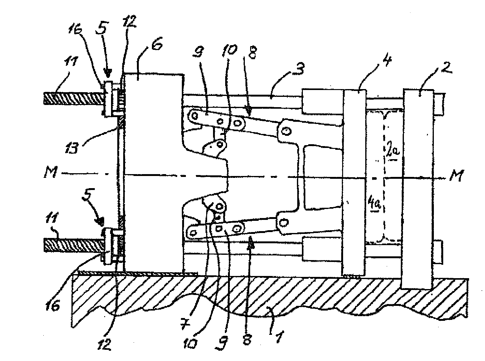
[0019] Turning now to the drawing, and in particular to FIG. 1, there is shown a side view of a mold clamping unit according to the present invention, constructed, by way of example, in the form of a three-platen machine. The mold clamping unit includes a first platen 2, which carries a half-mold 2a and is fixedly mounted onto a machine bed 1, a second platen 4, which carries...


PUM

PropertyMeasurementUnit
displacementaaaaaaaaaa
heightaaaaaaaaaa
lengthaaaaaaaaaa

Abstract

A mold clamping unit includes a mold height adjustment system having a length-adjustable threaded connection, comprised of a threaded spindle and a spindle nut which supports a platen of a molding tool, for stroke transmission and transmitting a locking force in clamping position. A clamping mechanism, which locks the spindle nut in relation to the threaded spindle and is selectively releasable for length adjustment of the threaded connection, includes a clamping nut, connected in fixed rotative engagement with and coupled for slight axial displacement in relation to the spindle nut, and an actuator, switchable between an active position, in which the spindle nut is braced with the clamping nut by a tightening force so that the platen is urged against the spindle nut, and an idle position, in which the actuator is released and which can be implemented irrespective of a stroke position of the drive mechanism. The threaded spindle and the platen are coupled to each other directly via the spindle nut for transmitting the clamping and locking forces, and via the actuator for transmitting an opening force in opposition to the clamping force.

Description

CROSS-REFERENCES TO RELATED APPLICATIONS [0001] This application is a continuation of prior filed copending PCT International application no. PCT / EP2005 / 052135, filed May 11, 2005, which designated the United States and has been published but not in English as International Publication No. WO 2006 / 003046 and on which priority is claimed under 35 U.S.C. §120, and which claims the priority of German Patent Application, Serial No. DE 10 2004 032 521.9, filed Jul. 6, 2004, pursuant to 35 U.S.C. 119(a)-(d), the contents of which are incorporated herein by reference in its entirety as if fully set forth herein.BACKGROUND OF THE INVENTION [0002] The present invention relates, in general, to the field of mold clamping units. [0003] Nothing in the following discussion of the state of the art is to be construed as an admission of prior art. [0004] German Pat. No. 101 61 911 C1 describes a mold clamping unit having a movable platen which is adjustably connected by means of a spindle nut to tie...

Claims


Application Information

Patent Timeline
Patent Type & Authority Applications(United States)
IPC IPC(8): B29C45/64B29C45/66B29C45/17
CPCB29C45/1751
Inventor DIENO, KURTKUBEL, ANDREAS
Owner SUMITOMO SHI DEMAG PLASTICS MACHINERY
Why Eureka
Try Eureka