Electric web fence

Active Publication Date: 2012-08-16
TWIN MOUNTAIN FENCE
View PDF22 Cites 4 Cited by
  • Summary
  • Abstract
  • Description
  • Claims
  • Application Information

AI Technical Summary

Benefits of technology

[0005]To minimize the energy required to energize the web for the particular livestock to be contained, galvanized wires are used in constructing the web. The coating of zinc of the galvanized wires lowers resistivity of th

Problems solved by technology

A person or animal touching both the wire and the earth during a pulse will complete an electrical circuit and conduct the pulse, causing an uncomfortable electric shock.
The effects of the shock depend upon the voltage, the energ

Method used


Image

  • Electric web fence
  • Electric web fence
  • Electric web fence

Examples


Example

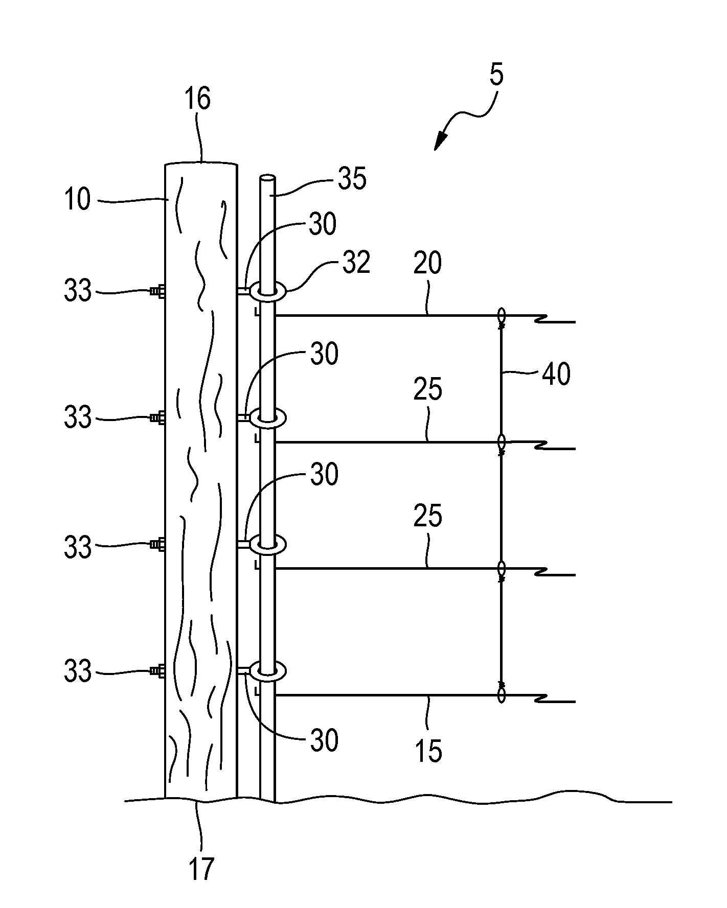
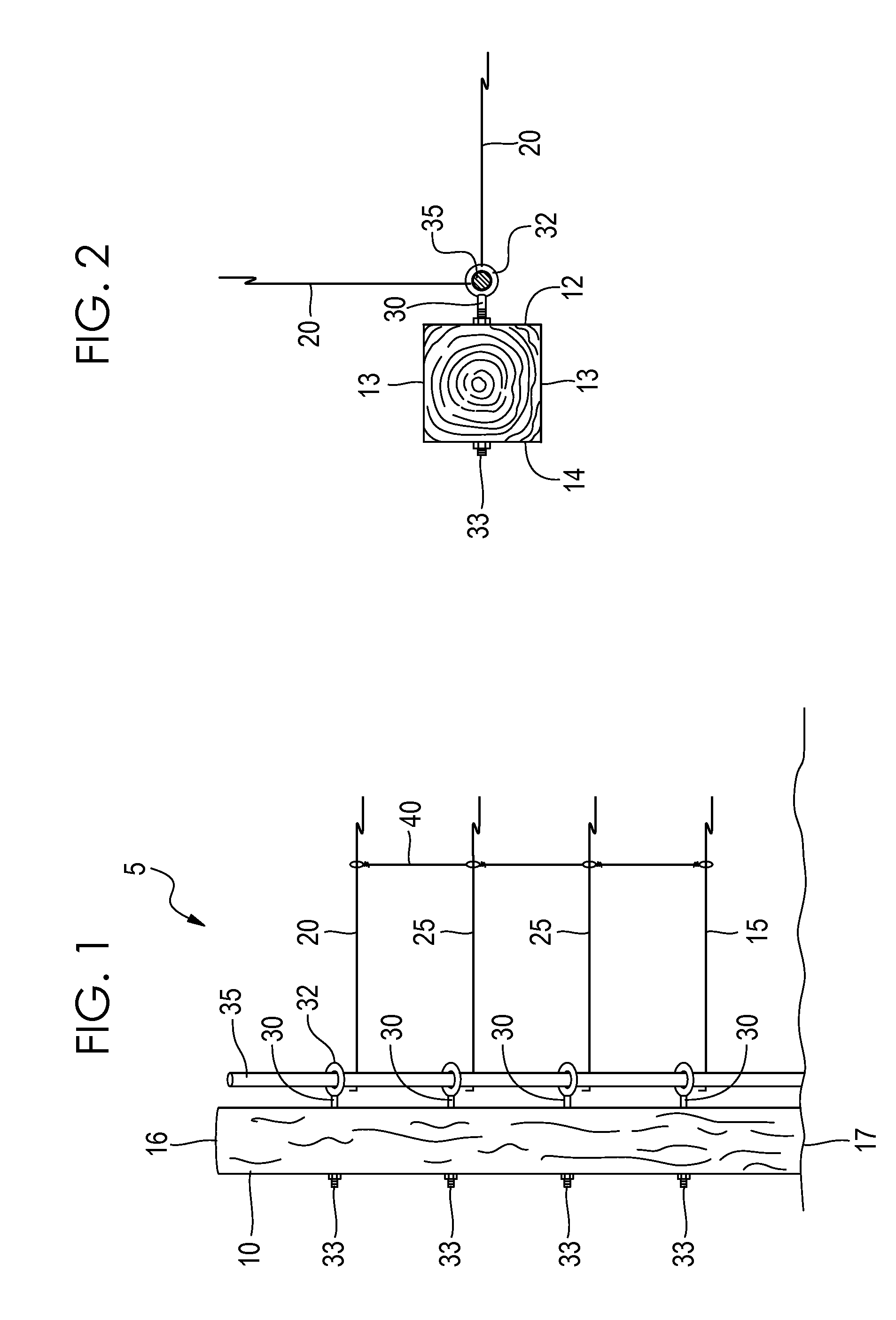
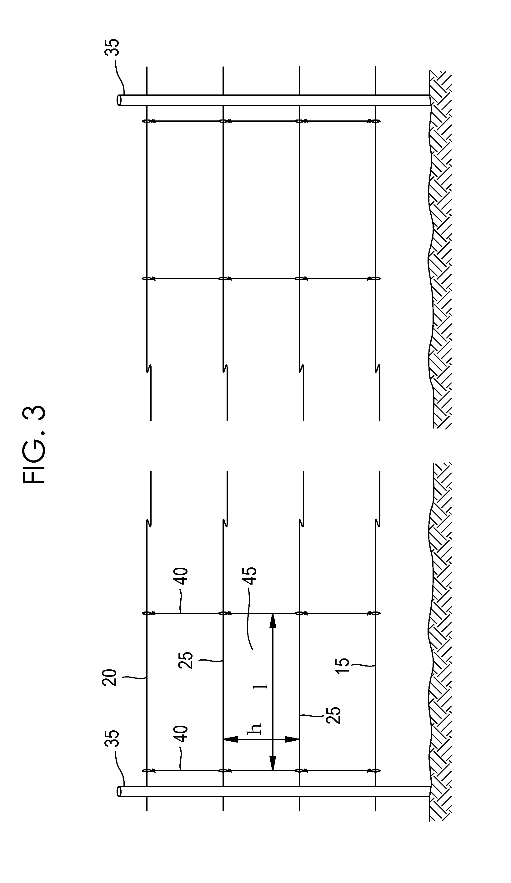
[0010]An electric fence 5 in accordance with the presently preferred embodiment of the present invention is illustrated in FIGS. 1 through 3, where like features of the invention share like numbering.

[0011]As illustrated in FIGS. 1 and 2, fence 5 generally includes a corner post 10 with a front side 12, a back side 14, two lateral sides 13, a top 16 and a bottom side 17. Post 10 may be composed of wood or other material and is fixed into the ground or braced at bottom side 17. In a preferred embodiment post 10 is composed of 6×6 pressure treated wood, meaning post 10 has a square cross-sectional shape as seen in FIG. 2 that is approximately 5.5 inches by 5.5 inches. The height of post 10 will vary depending on the livestock to be contained by the fence 5.

[0012]A plurality of fastening elements such as eye bolts 30 are coupled at regular intervals along the longitudinal axis of post 10. Eye bolts 30 as seen in FIG. 2 are composed of a ring body 32 encircling a ring opening, the ring ...


PUM

PropertyMeasurementUnit
Lengthaaaaaaaaaa
Lengthaaaaaaaaaa
Lengthaaaaaaaaaa

Abstract

An electric fence including a web of galvanized, high-tensile strength steel wires coupled to and between a pair of posts, the web including a plurality of substantially horizontally extending wires arranged substantially parallel to one another, and a plurality of substantially vertically extending wires arranged substantially parallel to one another and extending to and between each of the horizontally extending wires to form a plurality of wire rectangles, each rectangle having a desired size. The construction and arrangement of the web enables the web to be energized using less energy than conventional fencing.

Description

RELATED REFERENCES[0001]This application is a continuation-in-part of and claims priority to U.S. Provisional Patent Application Ser. No. 61 / 379,619, filed Sep. 2, 2010, the entire contents of which are incorporated herein by reference.FIELD OF INVENTION[0002]The present invention is directed to an electric fence system for containing livestock. More particularly, the present invention is directed to a fence having a webbed configuration constructed of galvanized, high-tensile strength wire and an energizer for electrifying the fence.BACKGROUND OF INVENTION[0003]Electric fences are designed to create an electrical circuit when touched by a person or animal. A component called a power energizer converts power into a brief high voltage pulse. One terminal of the power energizer releases an electrical pulse along a connected bare wire about once per second. Another terminal is connected to a metal rod implanted in the earth, called a ground or earth rod. A person or animal touching bot...

Claims


Application Information

Patent Timeline
IPC IPC(8): A01K3/00H01R43/00
CPCY10T29/49117A01K3/005
Inventor WALKER, RODNEY LYNNSTARNES, ANTHONY DAVIDNIELSEN, JOHN OLIVER
Owner TWIN MOUNTAIN FENCE
Why Eureka
Try Eureka