Modular rotary engine

a rotary engine and module technology, applied in the direction of rotary or oscillating piston engines, rotary piston engines, air transportation, etc., can solve the problems of low reciprocating mass, heat problems, friction, waste of materials, etc., to reduce internal friction, reduce the effect of reciprocating mass and short rang

Inactive Publication Date: 2008-03-18
LEON ENRIQUE HALUY
View PDF20 Cites 5 Cited by
  • Summary
  • Abstract
  • Description
  • Claims
  • Application Information

AI Technical Summary

Benefits of technology

[0014]Engine totally concentric and symmetric form; with only one major moving part in each module, with very low reciprocating mass and short range. Plus a reduced internal friction, results in a truly fuel saver machine. This device is disposed to reduce main internal friction, manually or electrically operated; let use rotor as part of an electric motor, giving in transport, recovery energy braking capability. It can also recover energy in form of compressed air.
[0015]High power / weight ratio, capable of producing multiple Otto cycles in every rotation, increasing those cycles exponentially when numbers of modules increase. Power increase adds low weight and volume of the engine and without increasing length of drive shaft, self-cooling avoid heat problems. Low RPM engine and vibration free, brings a durable device and adequate for use of hydrogen. Separated compression and expansion chambers, makes possible to use the heat of compression to avoid freezing when use compressed air as external energy source.
[0016]Best acceleration time, without flywheel and with development of Otto cycles in two times fashion. Fast exhausted gases evacuation means a more cool and less contaminant engine. Tuned port let use exhaust backpressure, bringing fuel savings and the staged output keep noise at minimum. Volumetric asymmetric ratio between compression and expansion chambers uses better the power of explosion and let a less violent output of exhausted gases.
[0017]The device is designed for a more efficient and integrated use of computer, electronics and electricity, providing more fast time response, more versatility and more accurate control. High reliability for aircraft use because few critical parts, low fuel consumption, high power density, vibration free and smooth torsion modulation.
[0018]Compression sharp peak, because of an almost wedge form of the chamber and fast switching to the expansion chamber makes adequate for auto ignition combustion, and also the mix compression at atmospheric pressure, or higher, can enable a homogeneous charge compression ignition.

Problems solved by technology

Nagata and Cobb, (U.S. Pat. No. 6,651,609) in recently few past years has itemized rotary engines, especially the Wankel engine, about its disadvantages, which are: vibration problems, heat problems, friction, mix wasted, difficult to build, inspect and maintain.
Almost of designs do not improves torsion, especially at low RPM, that implies work at high RPM regimen, with flywheels for kinetic energy storing, leading fuel waste when variation happens in acceleration.
Eccentricity and asymmetrical forms, typical in those engines leads to more fuel consumption, because compensatory mass is required; creating more vibrations and acceleration problems also.
Best power / weight ratio is hard to obtain, without increasing in the moving mass, heat and shaft length.
Need of gears and flywheels increase manufacturing costs, and also increase the engine overall weight.
Typically they are closed designs, purely mechanical solutions that do not allow changes.
Native flexibility scarce do no let obtain other improvements, as hydrogen fuel, compressed air, and neither other types of combustion can be used.
Use of modern resources as electricity, electronic, and computing have been very limited, because those developments were incorporated in adapted form, at existing designs that are from decades ago.
In transportation use, braking energy recovery is very difficult and not possible in some cases.

Method used


Image

  • Modular rotary engine
  • Modular rotary engine
  • Modular rotary engine

Examples


Embodiment Construction

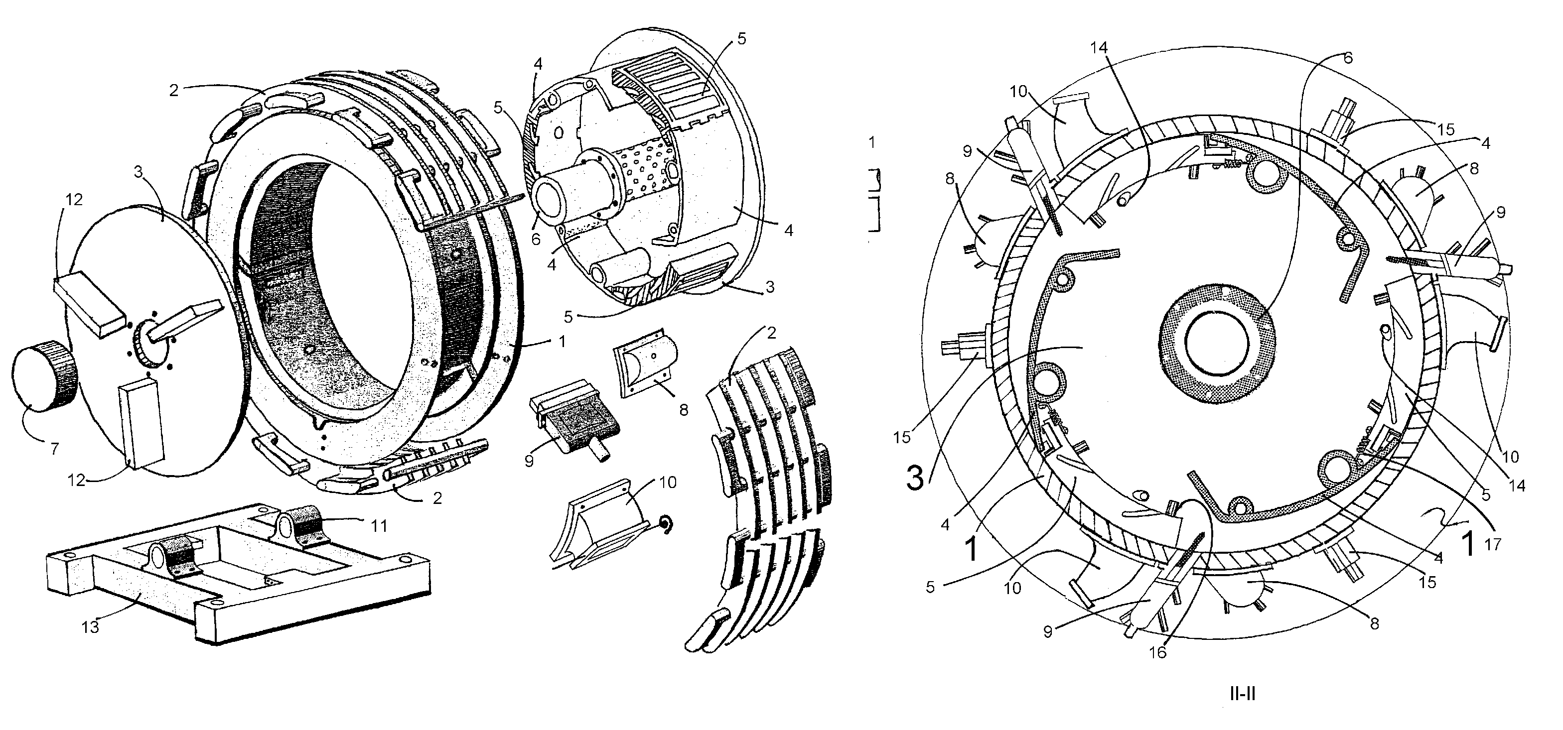
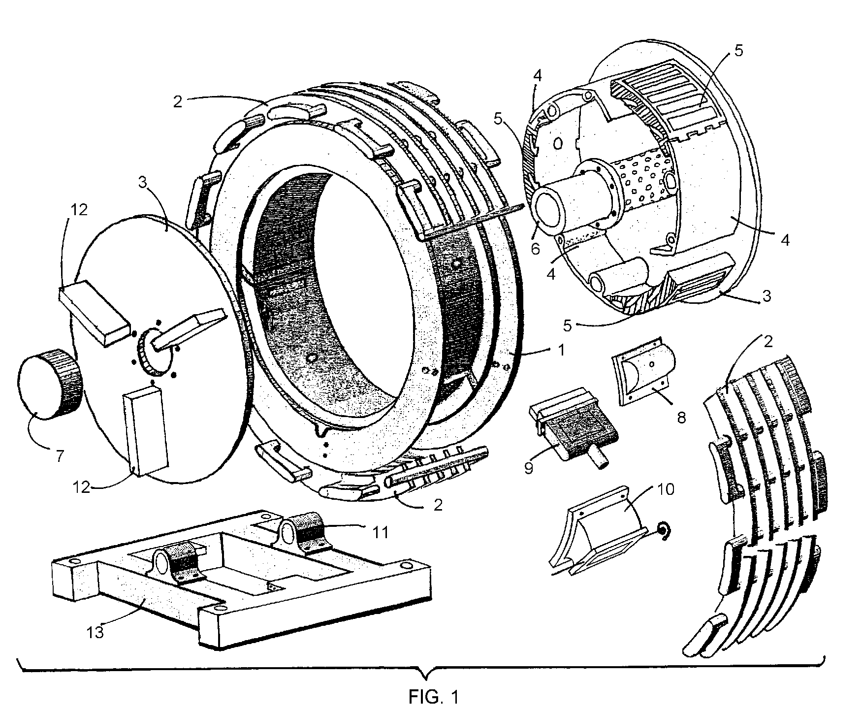
[0058]These engine works based on modules operating at the periphery of the rotor, each one consisting mainly of three chambers and one gate (9). and capable of using technology improvements in the areas of computing, electricity and electronics. A three module preferred embodiment is illustrated in the simplified expanded view in FIG. (1) and another cut view of the rotor inside the stator in FIG. (5) II-II, showing the main components.

[0059]Basically the engine has a stator (1), its form seems as a toroid of rectangular cross section (FIG. 18 cut VIII-VIII) where inside has solenoid gate valves (9), combustion chambers (8), and tuned ducts exhaust ports (10). Also contains all sort of standard parts used In Otto engines, such as sparkplugs (not showed), injectors (15), sensors (not showed) and a circular heat radiator (2).

[0060]It has a concentric rotor, reel resembling, in a short height cylinder form, with the wall formed by ramps (4), as vanes forms; jointed by a packer (25) an...


PUM


Abstract

An internal combustion device, rotor self cooled, concentric and symmetric shape, dynamically variable compression ratio; capable of developing multiple Otto cycles per rotation, using modules, each made, mainly of a solenoid gate valve and three chambers operating at the rotor periphery. High power / weight ratio, that improves substantially, by increasing quantity of working modules, and without any drive shaft lengthening. With volumetric asymmetry ratio between chambers, combustion gasses quick exhaust and fast rise of air / fuel mix pressure peak. Proper for many types of combustion and class of fuels, including hydrogen, and efficient use of compressed air as external energy supply. Excels in aircraft use.

Description

FIELD OF THE INVENTION[0001]This invention relates at field of rotary internal combustion engines, also is related with pneumatic engines.DESCRIPTION OF THE PRIOR ART[0002]Nagata and Cobb, (U.S. Pat. No. 6,651,609) in recently few past years has itemized rotary engines, especially the Wankel engine, about its disadvantages, which are: vibration problems, heat problems, friction, mix wasted, difficult to build, inspect and maintain.[0003]In general for all types of engines, is possible to add comments about another disadvantages as:[0004]Almost of designs do not improves torsion, especially at low RPM, that implies work at high RPM regimen, with flywheels for kinetic energy storing, leading fuel waste when variation happens in acceleration.[0005]No possibility to change compression ratio, that characteristic is wanted as altitude, load regimen, fuel class and combustion type.[0006]Eccentricity and asymmetrical forms, typical in those engines leads to more fuel consumption, because co...

Claims


Application Information

Patent Timeline
Patent Type & Authority Patents(United States)
IPC IPC(8): F02B53/04F01C1/00F02B57/00F04C18/00F04C2/00
CPCF01C1/3566F01D1/34Y02T50/671Y02T50/60
Inventor LEON, ENRIQUE HALUY
Owner LEON ENRIQUE HALUY
Why Eureka
Try Eureka