Space concentrator for advanced solar cells

a solar cell and space concentrator technology, applied in the field of solar concentrators, can solve the problems of limited effectiveness of cover glass protection, high-efficiency solar cells are expensive, and iii-v devices are also more expensive, and achieve the effect of reducing weigh

Inactive Publication Date: 2000-05-02
ORTABASI UGUR
View PDF6 Cites 119 Cited by
  • Summary
  • Abstract
  • Description
  • Claims
  • Application Information

AI Technical Summary

Benefits of technology

FIG. 14 is an enlarged view of the second stage, where the contour of the side walls of the bi-axial le

Problems solved by technology

Obviously, high efficiency solar cells, such as multijunction (MJ) cells, are preferably utilized; however, such high efficiency solar cells tend to be expensive.
However, such III-V devices are also more expensive, as compared with silicon solar cells.
However, the effectiveness of such cover glass protection is limited, and leads either to solar cell life limitations because the cover glasses have to be thin or to weight penalties if the cover glasses are made too thick.
Further, such cover glasses fail to provide any concentration of the solar ra

Method used


Image

  • Space concentrator for advanced solar cells
  • Space concentrator for advanced solar cells
  • Space concentrator for advanced solar cells

Examples


examples

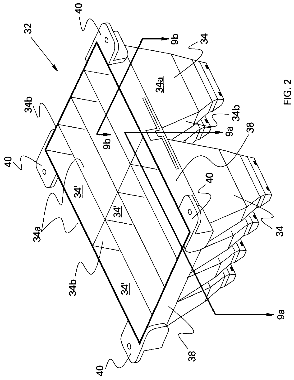
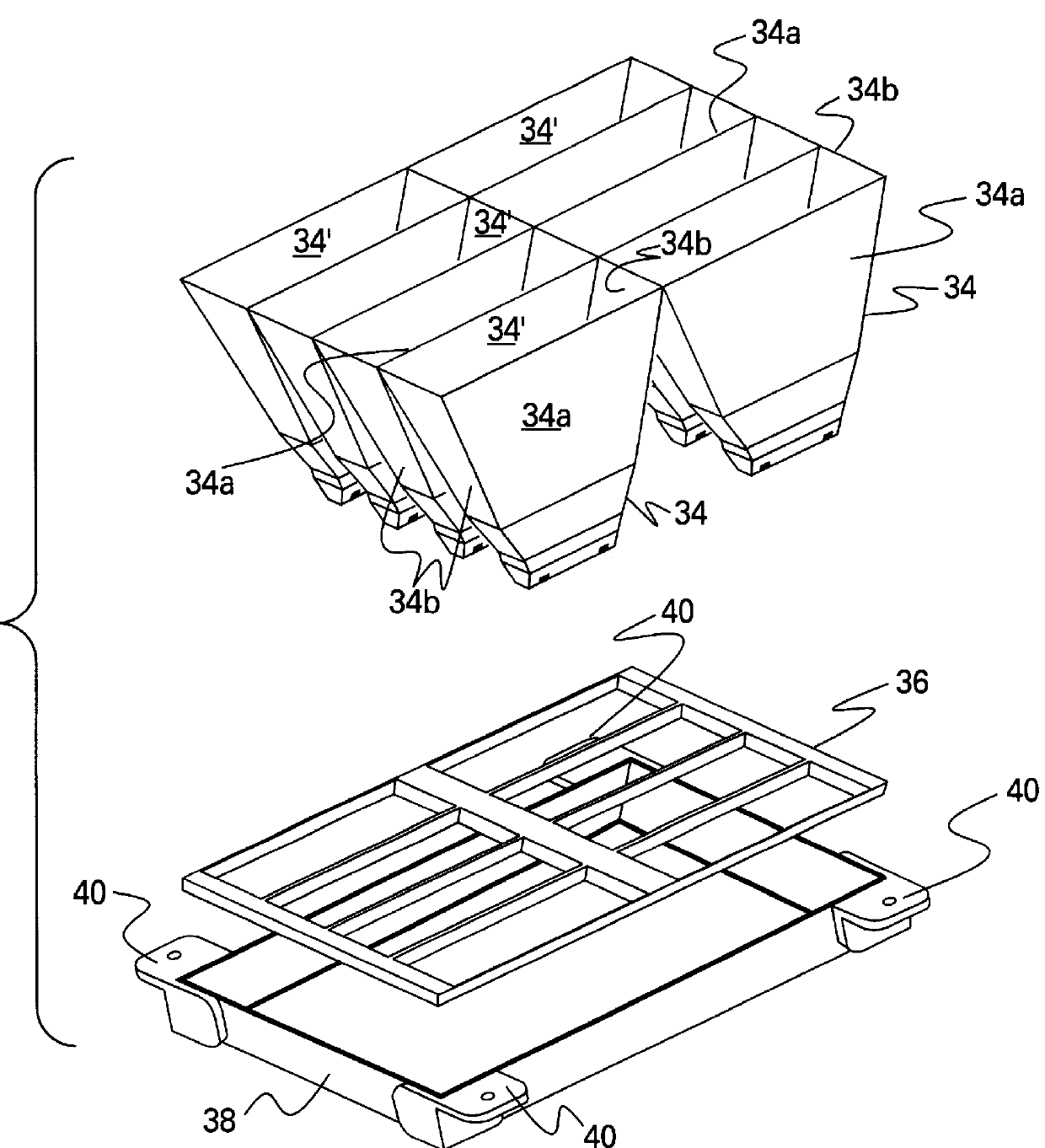
A sub-array 32 of two-stage concentrators of the invention, such as depicted in FIG. 2, was constructed, comprising an array of 2.times.4 concentrators. Each concentrator cusp 34 was 100 mm in length and 37.5 mm in width (at its entrance), and, with Bezier curves, was reduced to 40 mm in length and 16 mm in width (at the top of the bi-axial lens 44). The exit length of the bi-axial lens 44 was 30 mm and the exit width was 2.5 mm. The overall height of the concentrator cusp was 98 mm. The dimensions of the overall sub-array 32 was 203.1 mm.times.154 mm.

The inside surface 34' of the concentrator cusp 34 was provided with an aluminum coating 100 nm thick, which was covered with a silica coating 117 nm thick. An ITO layer 84 nm thick covered the silica coating. The average reflectance of the aluminum layer was determined to be about 93% over the wavelength range of .lambda.=350 nm and .lambda.=900 nm. Alternatively, a silver coating, 50 nm thick, coated with a silica coating 66 nm thick...


PUM


Abstract

A solar concentrator is provided that comprises two stages. The first stage comprises either a trough-shaped concentrator cusp unit having two major opposed sides joined by two ends. The inner surfaces of the first stage concentrator are mirrored. Further, the ends have two flat, angled surfaces, while the two sides have a Bezier-generated cylindrical shape that approximate parabolic surfaces followed by a straight section. The second stage comprises a bi-axial gradient refractive index (GRIN) element, in which two gradient refractive index materials, each having a high index surface and a low index surface, are joined together along their high index surfaces. The two ends of the bi-axial element are flat, while the two sides also have a Bezier-generated cylindrical shape that approximate parabolic surfaces followed by a straight section. The top surface of the bi-axial element is provided with a cylindrical surface, while the bottom, or exit, surface is ground flat. The high index boundary is parallel to the side surfaces of the first stage unit. A solar cell is bonded to the flat exit surface of the second stage of the concentrator of the present invention. An array of such concentrators and solar cells, in which the solar cells are electrically interconnected, may then be deployed for converting solar energy into useful electrical energy. The 2-D/3-D concentrator evidences much lower mass than prior art concentrators. Further, as the array, or panel, of solar cells wobbles in space, the concentrator will continue to operate, even at lower efficiencies, due to the larger acceptance angle. Concentration ratios on the order of 50x are realized with the present concentrator. However, design studies allow concentration ratios in excess of 300x when used with 3-D versions of the same concept. The second stage can comprise mirrored surfaces. Or, the first stage can comprise a conical section and the second stage a radial GRIN element.

Description

The present invention is directed to concentrators, each associated with a plurality of solar cells, for concentrating solar radiation by employing either trough-, trapezoidal-, and cone-shaped near-ideal, non-imaging concentrator elements, with or without a graded refractive index (GRIN) or a reflective second stage that replaces the refractive optics. The 2-dimensional version of the second stage may use a biaxial graded index of refraction profile, whereas the 3-dimensional version employing a cone-shaped first stage may use a radial index profile.Solar cells find extensive application in space-related vehicles for providing power from the sun. Obviously, high efficiency solar cells, such as multijunction (MJ) cells, are preferably utilized; however, such high efficiency solar cells tend to be expensive. Due to the high overall expense of satellite launch, deployment, and operation in space, it is desirable to extend the lifetime of the solar cells, whether in earth orbit, at var...

Claims


Application Information

Patent Timeline
IPC IPC(8): F24J2/06H01L31/06H01L31/052H01L31/068F24S23/00H01L31/0687
CPCF24J2/06F24J2/1047H01L31/0687H01L31/0547H01L31/0543F24J2002/1023Y02E10/52Y02E10/544Y02E10/44F24S23/80F24S23/00F24S2023/834
Inventor ORTABASI, UGUR
Owner ORTABASI UGUR
Why Eureka
Try Eureka