
Hub-mounted optical disk, method for fabricating optical disk, and injection molding die for manufacturing optical disk substrate

Inactive Publication Date: 2005-04-21
SAMSUNG ELECTRONICS CO LTD
View PDF8 Cites 2 Cited by
  • Summary
  • Abstract
  • Description
  • Claims
  • Application Information

AI Technical Summary

Benefits of technology

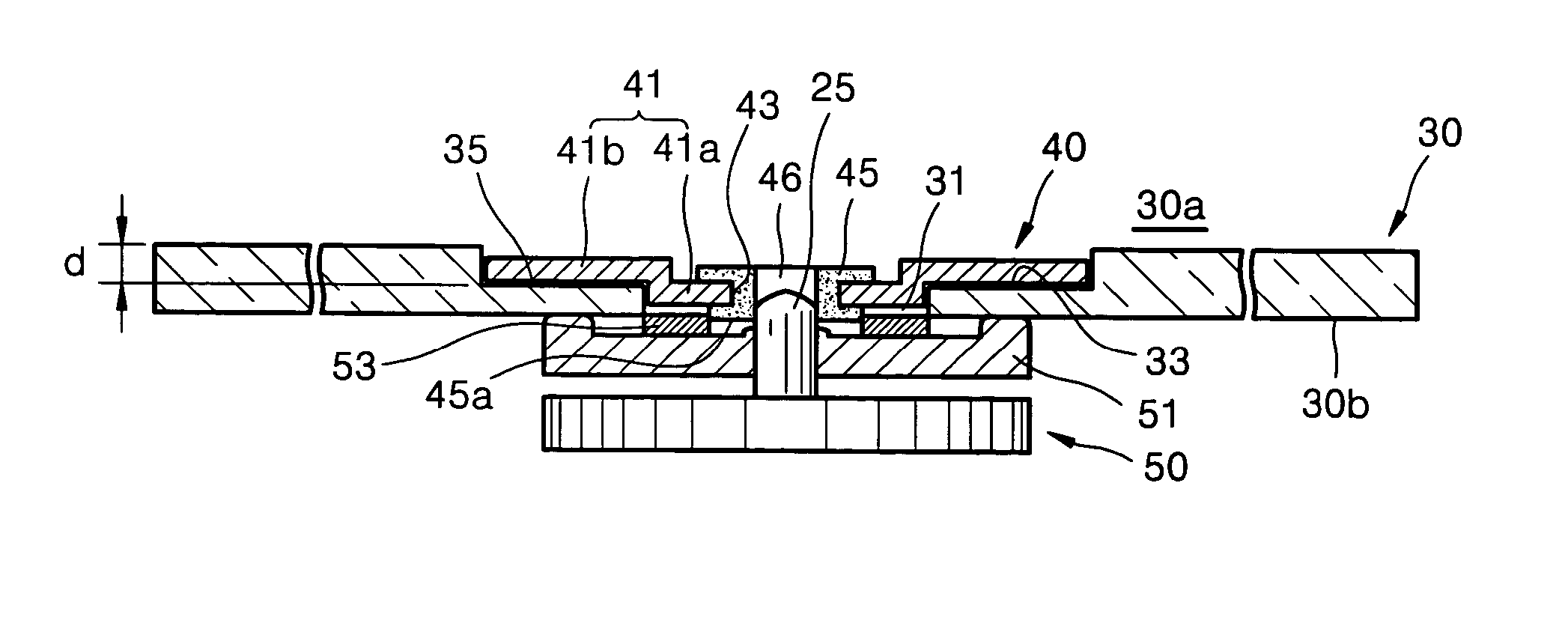
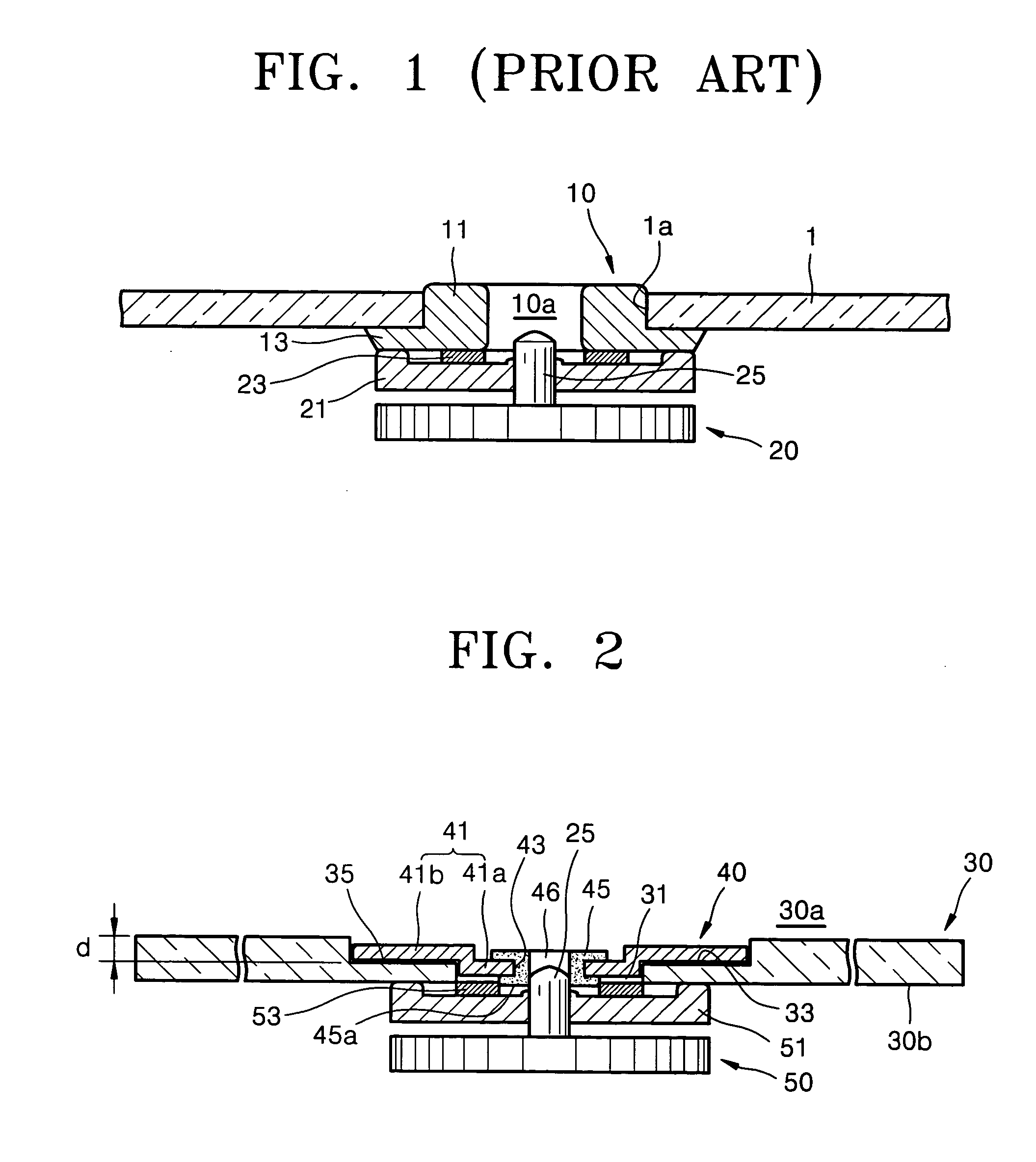
[0009] Therefore, the present invention provides a hub-mounted optical disk constructed to eliminate the need for a separate stack ring used to stack an optical disk substrate while decreasing the overall height.

Problems solved by technology

Here, the flange 13 projects toward one side of the substrate 1, which makes reducing the overall thickness of the optical disk and realizing a compact optical disk drive difficult.

Method used


Image

  • Hub-mounted optical disk, method for fabricating optical disk, and injection molding die for manufacturing optical disk substrate
  • Hub-mounted optical disk, method for fabricating optical disk, and injection molding die for manufacturing optical disk substrate
  • Hub-mounted optical disk, method for fabricating optical disk, and injection molding die for manufacturing optical disk substrate

Examples


Embodiment Construction

[0024] Reference will now be made in detail to the embodiments of the present invention, examples of which are illustrated in the accompanying drawings, wherein like reference numerals refer to the like elements throughout. The embodiments are described below to explain the present invention by referring to the figures.

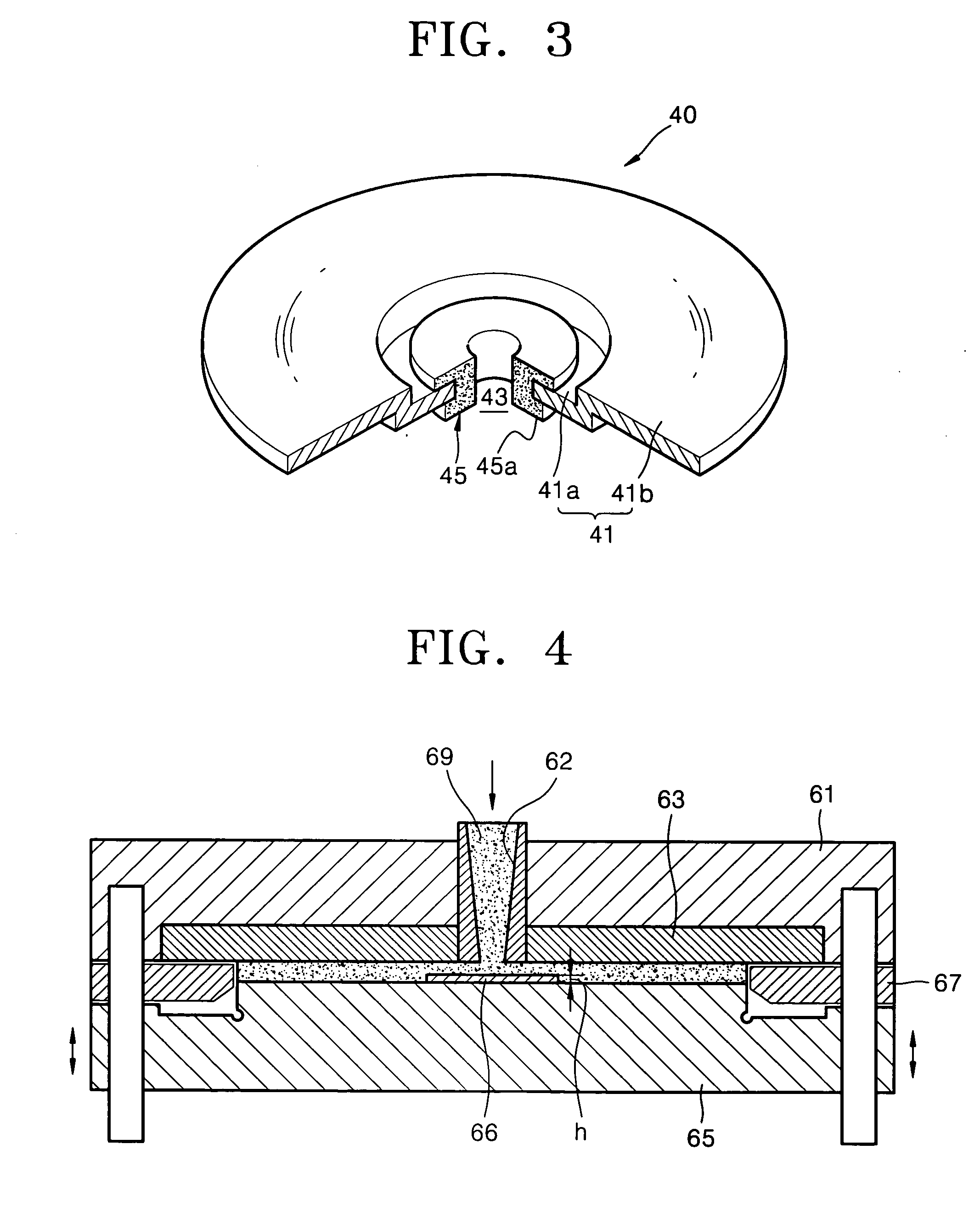
[0025] Referring to FIGS. 2 and 3, a hub-mounted optical disk according to an embodiment of the present invention includes a substrate 30 having a hollow 31 and a hub 40 mounted into the hollow 31 of the substrate 30. The substrate 30 has an indented portion 33 engraved to a predetermined depth on the inside of a non-recording surface 30a where no information is recorded. In an embodiment of the invention, a depth d of the indented portion 33 falls within a Range (1):

0.1≦d≦0.6 mm  (1)

[0026] Here, the range of the depth d is set such that the overall height of the optical disk combined with the hub 40 is not significantly greater than the thickness of the substrate ...


PUM


Abstract

A hub-mounted optical disk to eliminate the need for a separate stack ring while decreasing the overall height, a method of fabricating the optical disk, and an injection molding die for manufacturing an optical disk substrate. The hub-mounted optical disk includes a substrate having a hollow and an indented portion engraved to a predetermined depth on the inside of a non-recording surface where no information is recorded; and a hub including a plate that has a fitting hole therein and is engaged into the hollow and the indented portion and a central ring that is inserted into the fitting hole. The method of fabricating the hub-mounted optical disk includes mounting the hub onto a magnetic chuck, applying an ultra-violet (UV) hardening resin on the indented portion of the substrate, operating the magnetic chuck so that the plate is in contact with the indented portion, and curing the UV hardening resin by irradiating it with UV light. The injection molding die for manufacturing the optical disk substrate includes a stationary plate having an injection nozzle that allows resin forming the substrate to be injected, a stamper that has a predetermined information recording pattern, and a moving plate having a projecting portion at the center.

Description

CROSS-REFERENCE TO RELATED APPLICATION [0001] This application claims the priority of Korean Patent Application No. 2003-72797, filed on Oct. 18, 2003, in the Korean Intellectual Property Office, the disclosure of which is incorporated herein in its entirety by reference. BACKGROUND OF THE INVENTION [0002] 1. Field of the Invention [0003] The present invention relates to a hub-mounted optical disk that is magnetically mounted on a turntable, a method to fabricate the optical disk, and an injection molding die to manufacture an optical disk substrate, and more particularly, to a hub-mounted optical disk designed to eliminate the need for a separate stack ring while reducing the overall height, a method to fabricate the optical disk, and an injection molding die to manufacture an optical disk substrate. [0004] 2. Description of the Related Art [0005] Typically, a slim optical recording / reproducing apparatus employs a technique in which an optical disk is mounted on a turntable fixed t...

Claims


Application Information

Patent Timeline
IPC IPC(8): G11B7/26G11B23/00G11B25/04
CPCG11B23/0035G11B7/263G11B25/04
Inventor RO, MYONG-DOCHOI, HAN-KOOKJANG, DONG-SEOBYOON, DU-SEOP
Owner SAMSUNG ELECTRONICS CO LTD
Learn More