Sensor assembly, system including RFID sensor assemblies, and method

a sensor and sensor technology, applied in the field of sensors, can solve the problems of cost prohibitive adaptation of sensor networks and cabling infrastructures to existing plant environments, and achieve the effect of being ready to adap

Inactive Publication Date: 2005-04-28
BATTELLE MEMORIAL INST
View PDF22 Cites 169 Cited by
  • Summary
  • Abstract
  • Description
  • Claims
  • Application Information

AI Technical Summary

Problems solved by technology

Adapting a sensor network and its cabling infrastructure to existing plant environments is usually cost prohibitive.

Method used


Image

  • Sensor assembly, system including RFID sensor assemblies, and method
  • Sensor assembly, system including RFID sensor assemblies, and method
  • Sensor assembly, system including RFID sensor assemblies, and method

Examples


Embodiment Construction

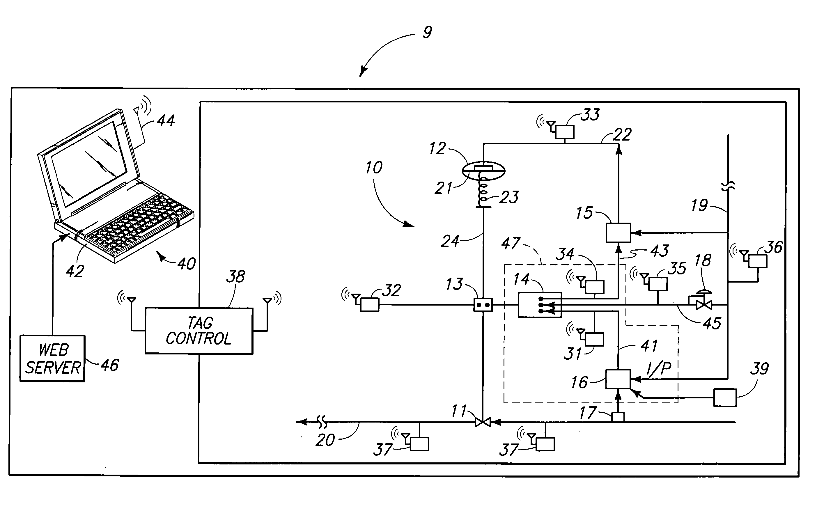
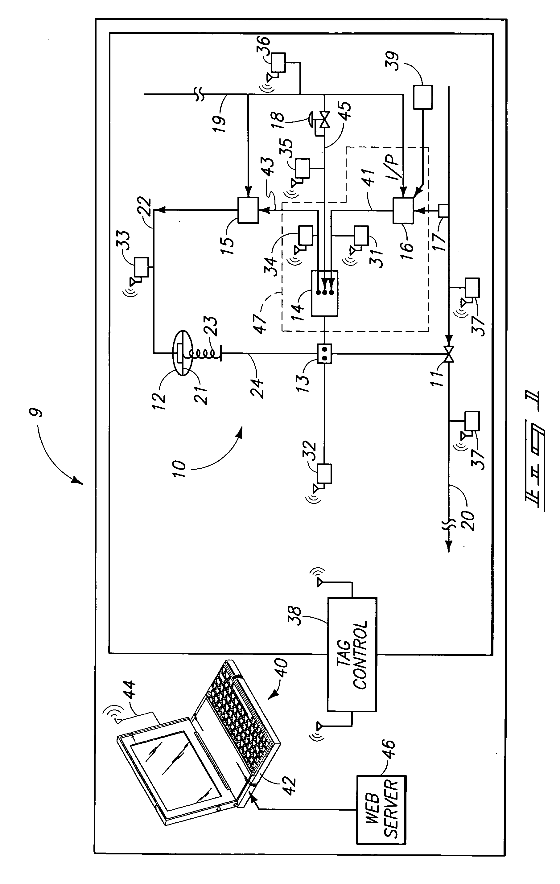
[0018]FIG. 1 shows a system embodying various aspects of the invention. The system 9 includes a fluid control or pneumatically operated valve 10. The air operated valve 10 includes a control valve 11, a pneumatic diaphragm actuator 12, a stem coupler 13, a valve positioner 14, a pressure or volume booster 15, a controller and I / P or E / P converter 16, a sensor 17, an air regulator 18, and a pneumatic fluid supply line 19. The valve 11 controls fluid flow through a main fluid line 20. The main fluid line 20 transfers fluid in connection with an industrial process. For example, the main fluid line could transfer fluid used in a power plant (e.g., water or other fluids used in a nuclear power plant). The fluid line 20 may be any other sort of fluid line in an industrial process facility.

[0019] In the illustrated embodiment, a condition of the fluid line 20 is sensed (e.g., temperature, pressure, flow) and this information is sent to the valve positioner 14. For example, in the illustra...


PUM


Abstract

A system comprises a valve; a plurality of RFID sensor assemblies coupled to the valve to monitor a plurality of parameters associated with the valve; a control tag configured to wirelessly communicate with the respective tags that are coupled to the valve, the control tag being further configured to communicate with an RF reader; and an RF reader configured to selectively communicate with the control tag, the reader including an RF receiver. Other systems and methods are also provided.

Description

GOVERNMENT RIGHTS [0001] This invention was made with government support under contract number DE-AC0676RL01830 awarded by the U.S. Department of Energy. The Government has certain rights in the invention.TECHNICAL FIELD [0002] The invention relates to sensors. The invention also relates to valves and process control. BACKGROUND OF THE INVENTION [0003] Industrial process control environments typically require physical sensing of parameters such as temperature, pressure, flow rate, strain, displacement, humidity, vibration, etc. Adapting a sensor network and its cabling infrastructure to existing plant environments is usually cost prohibitive. [0004] Various sensors that incorporate transmitters are known in the art. For example, U.S. Pat. No. 5,774,048 (incorporated herein by reference) relates to a valve that generates a wireless transmittable signal if pressure drops within vehicle tires. U.S. Pat. No. 6,005,480 to Banzhof et al. relates to similar subject matter. [0005] U.S. Pat....

Claims


Application Information

Patent Timeline
Patent Type & Authority Applications(United States)
IPC IPC(8): F16K37/00G05B23/02
CPCF16K37/00Y10T137/8242
Inventor SKORPIK, JAMES R.GOSSELIN, STEPHEN R.HARRIS, JOE C.
Owner BATTELLE MEMORIAL INST
Why Eureka
Try Eureka