
Pump pulsation dampening attachment and method for dampening pump pulsations

a technology of pump pulsation and attachment, which is applied in the direction of pulse equalisation, pump components, positive displacement liquid engines, etc., can solve the problems of excessive wear, difficult to achieve precise and accurate flow rates in such systems, and the typical generation of significant pressure surges by positive displacement pumps, so as to reduce manufacturing costs, quick and efficient fluid delivery, and minimize the effect of flow pulsation

Inactive Publication Date: 2005-04-28
COTT TECH
View PDF18 Cites 17 Cited by
  • Summary
  • Abstract
  • Description
  • Claims
  • Application Information

AI Technical Summary

Benefits of technology

[0015] It is a further object of the invention to provide such a pump delivery system that facilitates the efficient delivery of fluids by providing a pump pulsation dampening attachment that dampens the pulsating flow output generated by the pump mechanism.
[0017] It is still another object the invention to provide such a pump delivery system that facilitates effective cleaning-in-place (CIP).
[0024] Accordingly, the pump delivery system in accordance with the invention is advantageous in being adaptable to quickly and efficiently deliver fluids by minimizing flow pulsations caused by the pulsing output of the pump mechanism. The pump delivery system is also advantageous in reducing manufacturing costs and increasing production. The pump delivery system is further advantageous in providing a system that meets FDA standards in facilitating the cleaning-in-place of the interior surface of the pressurized vessel.

Problems solved by technology

While these prior art systems are sometimes adequate for certain applications, precise and accurate flow rates in such systems are difficult to achieve due to the pulsing, surging, or hydraulic shock generated by the output of the pump mechanism, which also must be comparable with CIP facilities.
For example, positive displacement pumps typically generate significant pressure surges due to the rapid acceleration and deceleration of the liquid during the sinusoidal cycle of the pump.
Such pulsing, surging or otherwise hydraulic shock is undesirable since it typically results in hydraulic hammer in process lines, large pressure fluctuations, excessive wear and increased cost of maintenance of pumps and instruments, inaccurate flow rates during delivery operations, which results in increased production costs production time.
The pressurized tank of Vogt, however, is not adaptable for standard pumps with mechanical pumps such as cylinders, as they are found to be unsuitable since they permit the occurrence of undesirable contaminates.
Accordingly, the tank in Vogt cannot accommodate a wide range of pumps and pumping systems in which pump pulsating output is variable.
The tank also lacks a sensing mechanism for monitoring and adjusting the air-to-liquid ratio in the dampening chamber and is not sized to correspond to the duration and intensity level of the pulsating output.
The tank of Shannon, however, does not include a sensing mechanism for monitoring and adjusting the air-to-liquid ratio in the dampening chamber and is not sized to correspond to the duration and intensity level of the pulsating output.
The tank is also not adaptable for use in combination with a wide range of pumps and pumping systems in which pump pulsating output is variable.
Conatser, however, does not include CIP or a sensing mechanism for monitoring and adjusting the air-to-liquid ratio in the dampening chamber.
Mercier, however, lacks CIP or probes or sensing devices for accommodating the ratio between the air and liquid.
Many prior art systems are also not adaptable for use in sanitary filling operations since they lack a pump pulsation dampening assembly that also meets the cleaning-in-place standards required by the FDA.
The prior art also fails to provide an attachment for accommodating a wide range of pumps and pumping systems or a method of dampening pulsations resulting from the operation of various pumps.
The prior art also lacks a device that monitors and adjusts the air-to-liquid ratio inside a pump pulsation dampening attachment in response to the duration and intensity of the pulsating fluid flow.

Method used


Image

  • Pump pulsation dampening attachment and method for dampening pump pulsations
  • Pump pulsation dampening attachment and method for dampening pump pulsations
  • Pump pulsation dampening attachment and method for dampening pump pulsations

Examples


Embodiment Construction

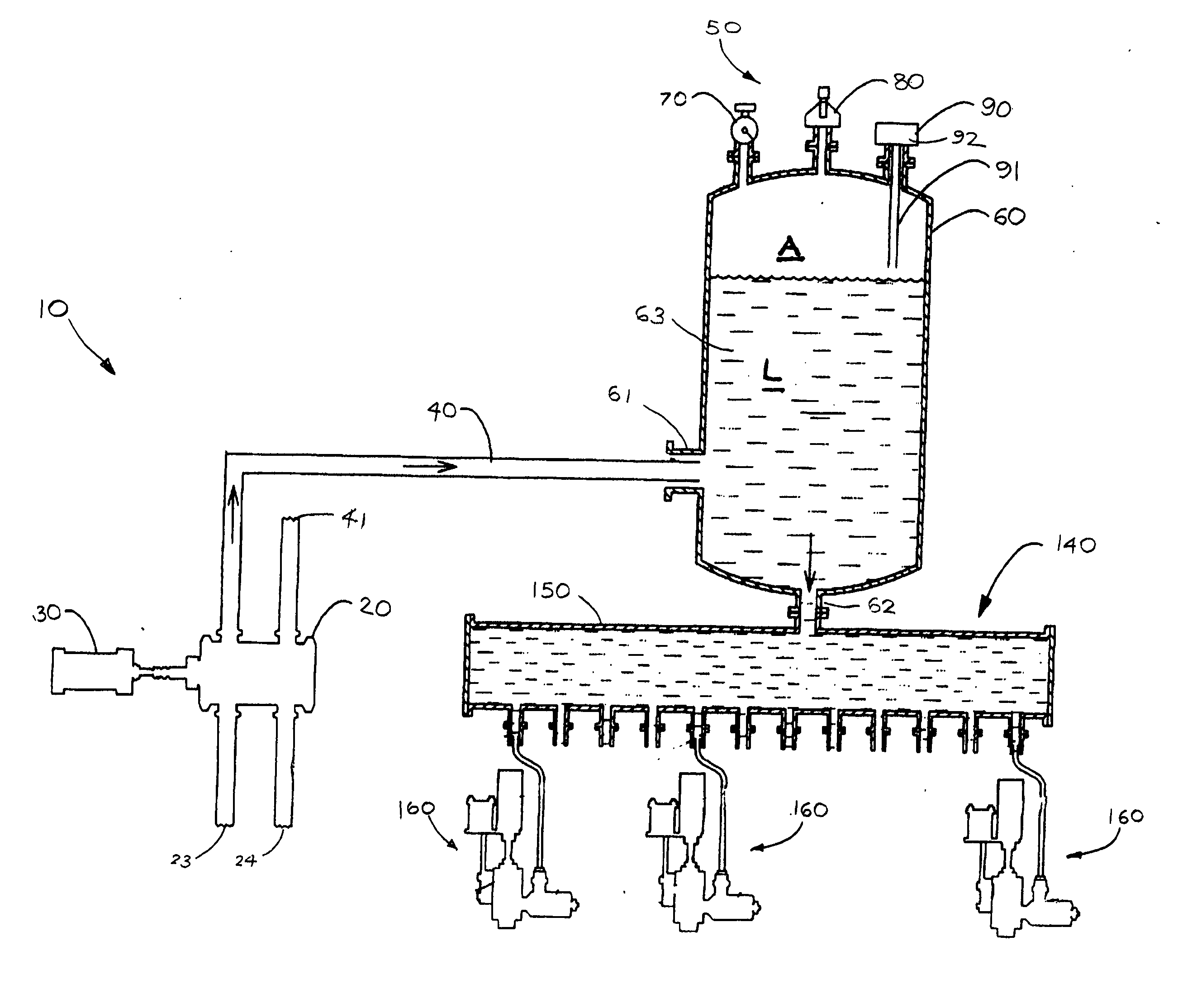
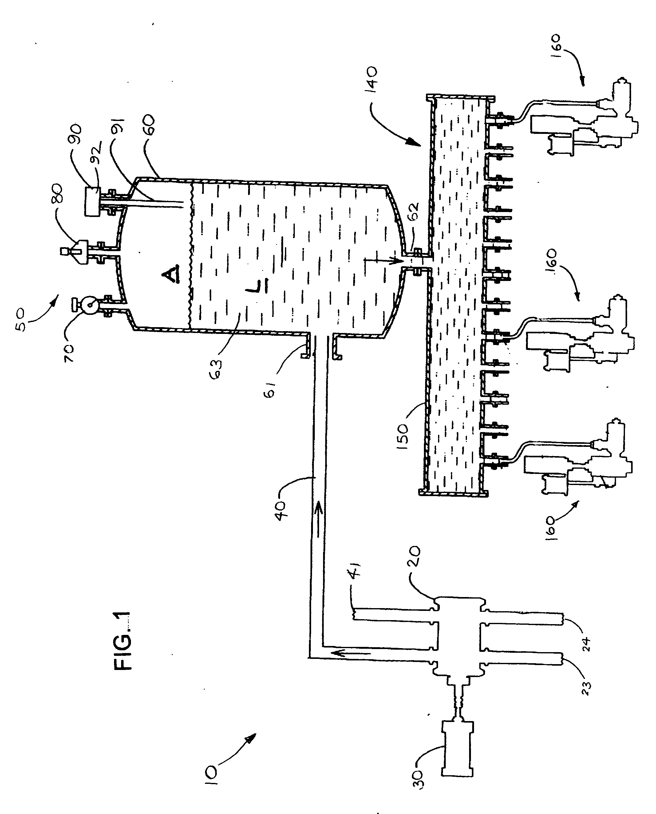
[0041] As shown in FIG. 1, in a first embodiment of the invention, a pump delivery system 10 adapted for use in a sanitary filling operation that includes a filling machine 140 whereby a viscous fluid or liquid (L) is delivered to a fluid manifold 150 in communication with a plurality of fill heads 160 which dispense the fluid to respective containers (not shown).

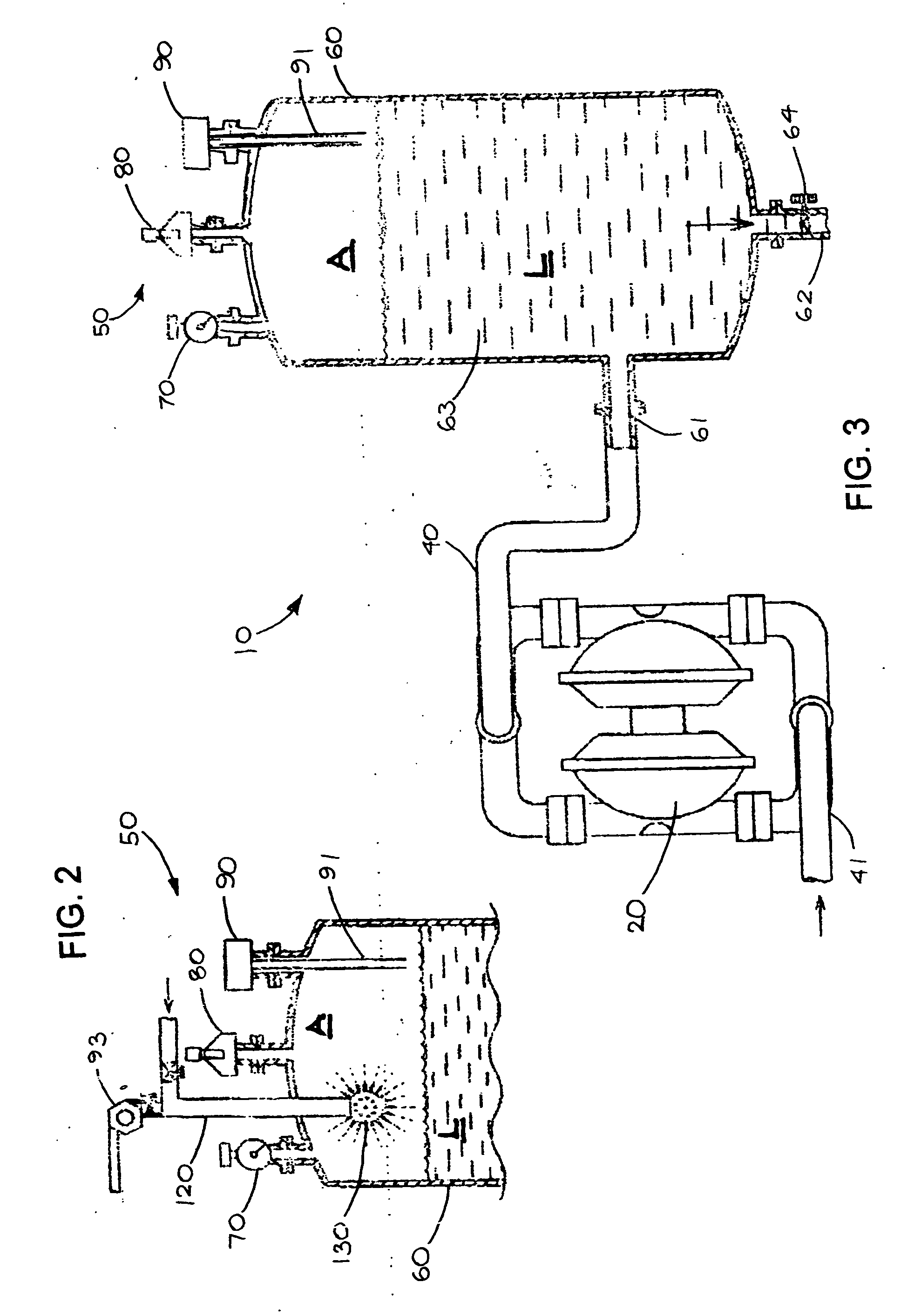
[0042] As shown in FIGS. 1, 6, 8 and 13, the pump delivery system 10 of the invention includes a pump mechanism 20 mechanically driven by a motor 30 for delivering the liquid (L) under pressure to the filling machine 140, the pump mechanism 20 generating a pulsating output during operation. As shown in FIGS. 1 and 11, the pump mechanism 10 may include a double acting piston head 21 driven by a drive shaft 22 having a pair of inlet ports 23, 24 for receiving the liquid (L) and a pair of outlet ports 40, 41 in communication with a pump pulsation dampening attachment or assembly 50 for transporting the liquid (L) thereto. As ...


PUM


Abstract

A pump delivery system including a pump mechanism for delivering liquids under pressure while also producing a pulsating output during operation, and a pump pulsation dampening attachment for dampening the pulsating output of the pump mechanism. The pump pulsation dampening assembly includes a pressurized vessel having an interior surface defining a chamber for receiving the liquid from the pump mechanism, the chamber also containing a pocket of pressurized air therein for absorbing the pulsating output generated by the pump mechanism.

Description

BACKGROUND OF THE INVENTION [0001] 1. Field of the Invention [0002] This invention relates generally to a pump delivery system adaptable to dampen the pulsating flow or hydraulic shock caused as result of the intermittent nature or the idle period of the pump mechanism and also adaptable for use in sanitary filling operations. More particularly, the invention relates to a hydraulic shock absorbing attachment adaptable to substantially dampen pulsations resulting from the operation of various pumps including constant pressure pumps for the high-speed delivery of precisely measurable quantities of liquids. [0003] 2. Description of the Related Art [0004] A wide variety of industrial applications, especially in the pharmaceutical and food processing industries require high-speed fluid metering and pumping systems capable of delivering precisely measured quantities of fluids at accurate flow rates to various locations. Sanitary filling operations require that sanitary pumping systems pro...

Claims


Application Information

Patent Timeline
Patent Type & Authority Applications(United States)
IPC IPC(8): F04B11/00F16L55/052
CPCF16L55/052F04B11/0025
Inventor NAVARRO, RAMON M.
Owner COTT TECH
Learn More