
System, tracker, and program product to facilitate and verify proper target alignment for radiation delivery, and related methods

a technology of target alignment and program product, applied in the field of patient therapy, can solve the problems of serious complications, radiation dose may not be delivered to the correct location within the patient's body, and the use of the necessary effective radiation dose, and achieve the effect of simple and quick applications

Active Publication Date: 2006-12-21
BEST MEDICAL INT
View PDF21 Cites 114 Cited by
  • Summary
  • Abstract
  • Description
  • Claims
  • Application Information

AI Technical Summary

Benefits of technology

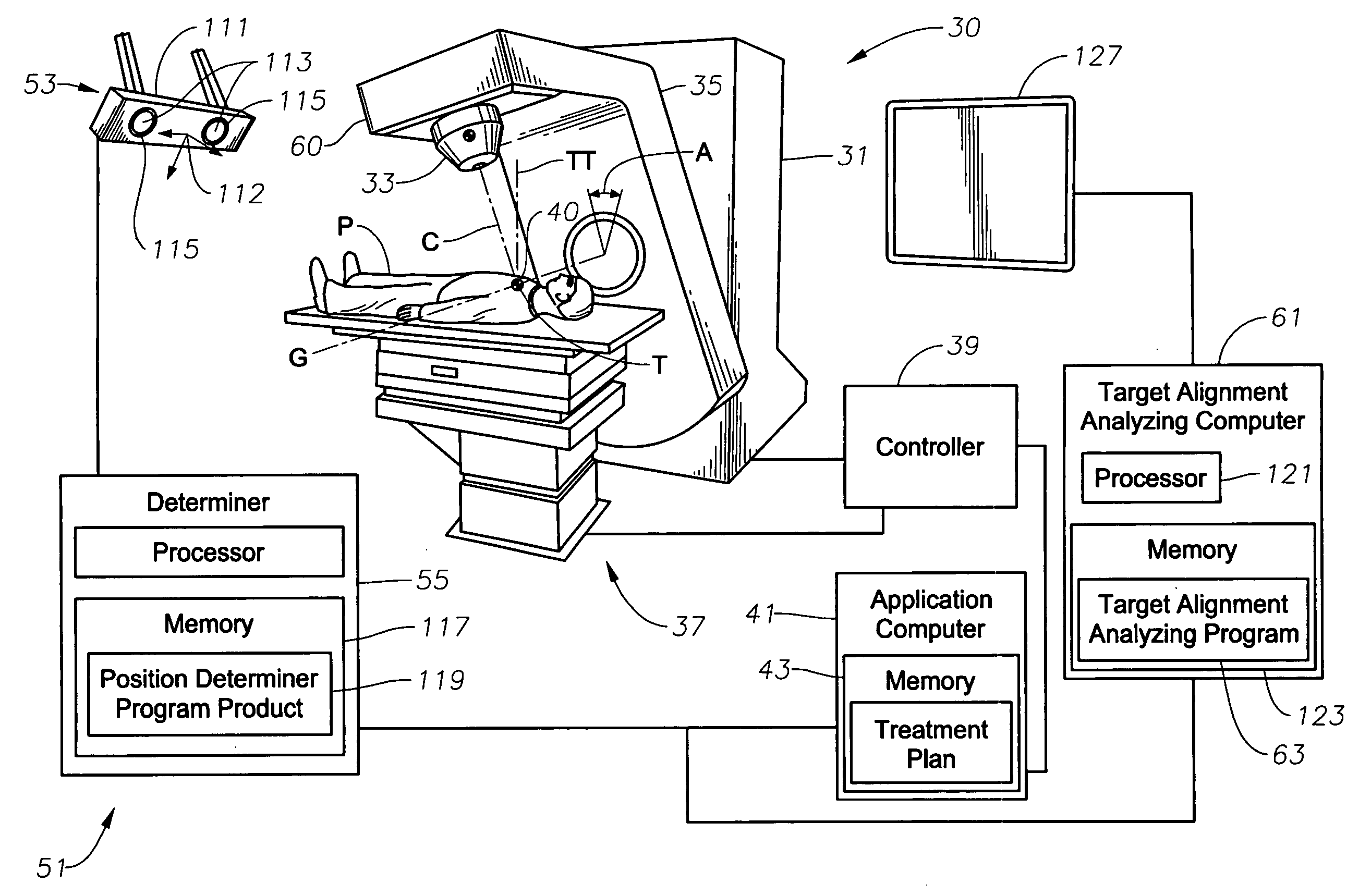
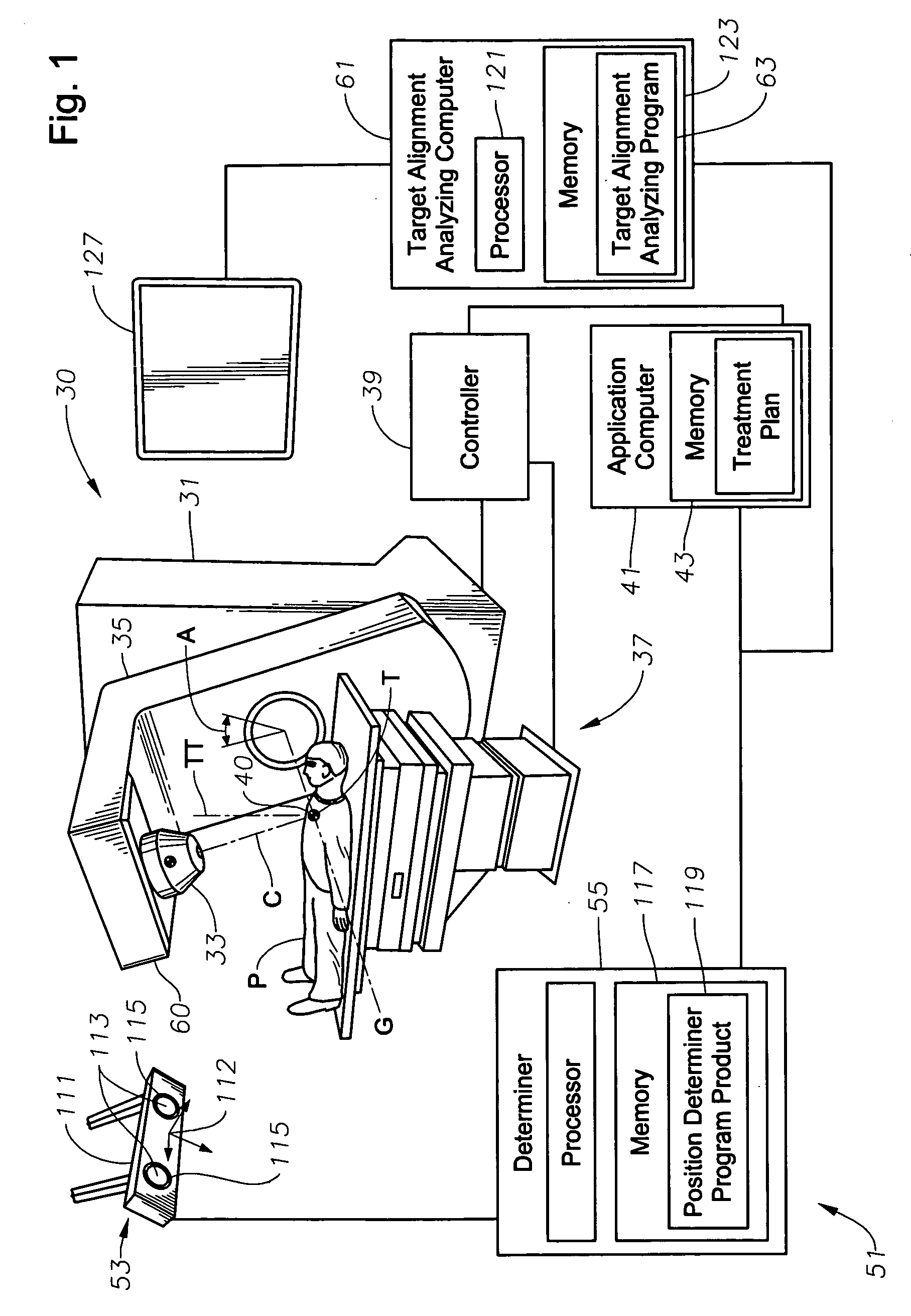
[0017] In view of the foregoing, embodiments of the present invention advantageously provide a system including tracker, program product, and related methods to facilitate and verify proper target alignment for radiation delivery from a radiation delivery apparatus having a radiation emitter so that a treatment plan can be more accurately applied to a patient. Embodiments of the present invention provide a system including tracker, program product, and related methods that can provide a source-to-surface distance SSD between a theoretical point source of the radiation delivery emitter and a surface of the patient whether the surface is planer or whether the surface has a substantial slope or gradient. This SSD can be used to calibrate the actual patient's position with the patient's position according to the treatment plan, so that the treatment plan can be more accurately applied. Embodiments of the present invention provide a system including tracker, program product, and related methods that can quickly and efficiently deliver an SSD measurement for each of multiple surfaces of the patient without requiring repositioning of the patient in order to take each individual reading. This advantageously provides a significant time-saving advantage over the use of the optical distance indicators (ODIs).
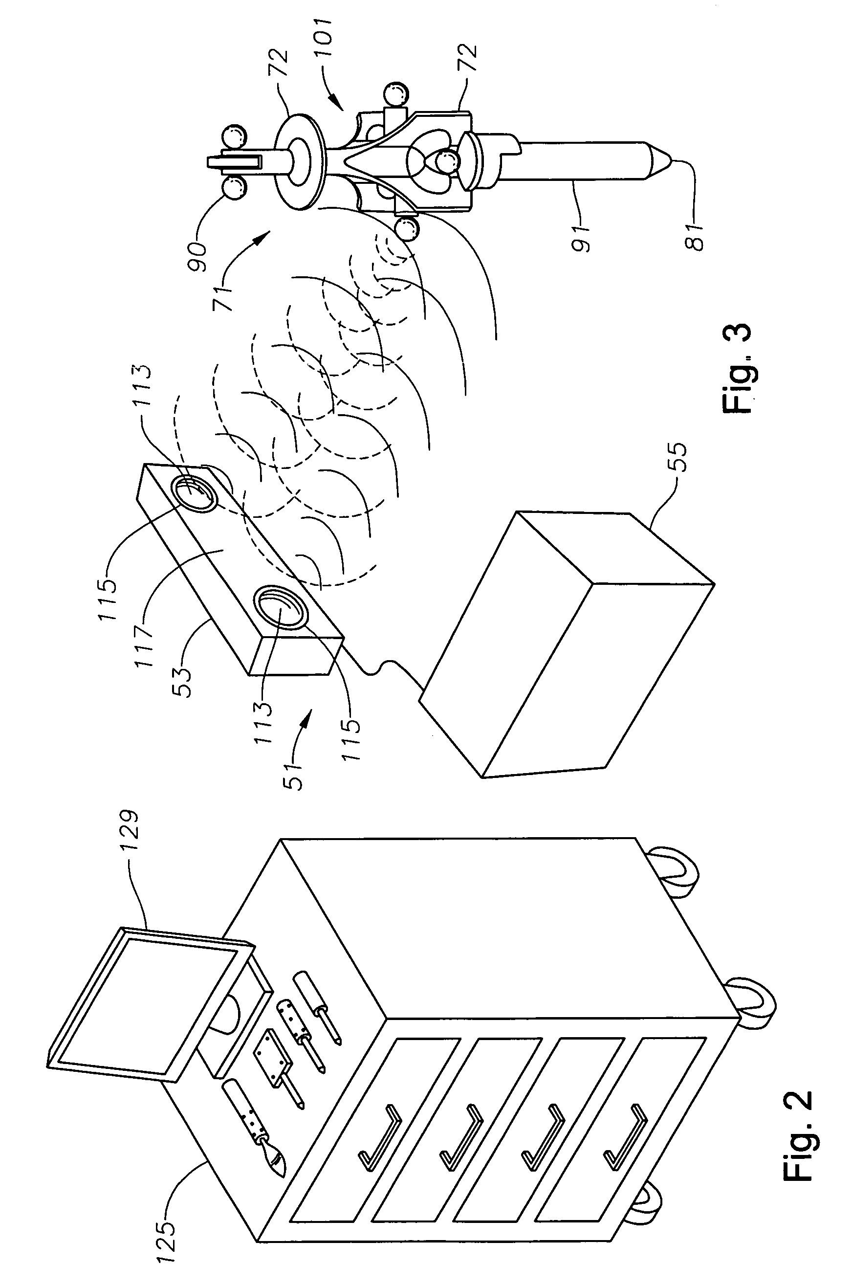
[0018] Embodiments of the present invention further provide a system including tracker, program product, and related methods that can deliver actual SSD measurements for surfaces of the patient obstructed by various structures, including the rotating table assembly of the linear accelerator when such radiation delivery apparatus is used, and can provide accurate SSD and patient thickness measurements for measurement points opposite each other along the central axis of the radiation extending through the isocenter of the radiation delivery apparatus. Embodiments of the present invention also provide a system including tracker, program product, and related methods that can accurately provide measurement data for a contoured portion of the patient's anatomy and that can help determine required radiation beam angles, beam field size, and location of the edges of the beam field. Embodiments of the present invention still further provide a system including tracker, program product, and related methods that can be used whether or not a MIMiC is mounted to the rotating gantry assembly of a linear accelerator when such radiation delivery apparatus is used, and that preferably does not require individual calibration.

Problems solved by technology

Complications, however, may result from use of the necessary effective radiation dose, due to damage to healthy tissue which surrounds the target or to other healthy body organs located close to the target.
If the effective radiation dose is not delivered to the proper location within the patient, serious complications may result.
If the position of the target is not the same as it was at the time the treatment plan was determined, the dose of radiation may not be delivered to the correct location within the patient's body.
Because patients are not always positioned properly on the treatment table of the radiation therapy device, which may be a linear accelerator or a cobalt unit, for example, and because organs of a patient may move within the patient from day to day, the target may not be positioned at the exact location where the radiation therapy plan has assumed it would be located.
Recognized by the Applicant, however, is that the slope or gradient of the patients skin, e.g., at the neck or along a breast, often makes the scale hard, if not impossible, to read.
Also recognized by the Applicant is that readings can only be taken when there is unobstructed line of sight between the head of the radiation delivery apparatus and the patient's skin, making it impossible to take direct measurements of positions underneath the patient, e.g., behind the patient's neck.
Further, recognized by the Applicant is that the scale frequently requires calibration, resulting in an expenditure of valuable resources.
Recognized by the Applicant is that this process of moving the patient to directly beneath the rotating gantry head and the rotating gantry assembly so that the ODI will shine on the selected measurement point can be very time consuming.
ODI readings can only be taken where there is unobstructed line of sight between the head of the radiation delivery apparatus and the patient's skin, making it impossible to take direct measurements of positions underneath the patient, e.g., behind the patient's neck.
Recognized by the Applicant, however, is that there are no precise aids to ensure that the calipers are measuring points that are directly opposite each other along the central axis of the radiation beam.
Recognized also is the inherent inaccuracy of having such potentially imprecise caliper scale increments.
Recognized by the Applicant is that this type of contoured anatomy setup disadvantageously can take as long as 15 or 20 minutes and requires a fluoroscopy procedure which radiates the patient.

Method used


Image

  • System, tracker, and program product to facilitate and verify proper target alignment for radiation delivery, and related methods
  • System, tracker, and program product to facilitate and verify proper target alignment for radiation delivery, and related methods
  • System, tracker, and program product to facilitate and verify proper target alignment for radiation delivery, and related methods

Examples


Embodiment Construction

[0084] The present invention will now be described more fully hereinafter with reference to the accompanying drawings, which illustrate embodiments of the invention. This invention may, however, be embodied in many different forms and should not be construed as limited to the illustrated embodiments set forth herein. Rather, these embodiments are provided so that this disclosure will be thorough and complete, and will fully convey the scope of the invention to those skilled in the art. Like numbers refer to like elements throughout. Prime notation, if used, indicates similar elements in alternative embodiments.

[0085] Successful therapy treatments, such as, for example, radiation therapy, rely on the ability to accurately locate and define a radiation beam. The spatial position of the radiation beam is defined by the physical geometry of the treatment apparatus. The geometry of rotating assemblies of the treatment apparatus define a coordinate system of the treatment apparatus, whic...


PUM


Abstract

A system, tracker, program product, and methods to facilitate and verify proper target alignment for radiation delivery are provided. The system includes a radiation delivery apparatus having a radiation emitter, a rotating assembly controlled by a controller, and an application computer which provides treatment delivery instructions to the controller. The system also includes a trackable body having a trackable body reference point to be positioned adjacent a surface point of a patient to determine a position of such surface point. The system also includes an apparatus to track a trackable body which has a trackable body detector to detect a position of indicators carried by the trackable body and a trackable body determiner to determine a position of the trackable body reference point. The system also includes a target alignment analyzing computer having memory and target alignment analyzing program product stored therein to aid a user of the system to make and display various patient body-surface related measurements.

Description

1. RELATED APPLICATIONS [0001] This application claims priority to and the benefit of U.S. Provisional Application No. 60 / 691,027, filed on Jun. 16, 2005, incorporated herein by reference in its entirety.BACKGROUND OF THE INVENTION [0002] 2. Field of the Invention [0003] The present invention relates to patient therapy. More specifically, the present invention relates to a system, tracker, program product, and related methods to facilitate and verify proper target alignment for radiation delivery so that a treatment plan can be more accurately applied to a patient. [0004] 3. Description of the Related Art [0005] Radiation therapy can be effective in treating certain types of cancerous tumors, lesions, or other “targets.” A vast majority of such targets can be eradicated completely if a sufficient radiation dose is delivered to the tumor or lesion volume. Complications, however, may result from use of the necessary effective radiation dose, due to damage to healthy tissue which surro...

Claims


Application Information

Patent Timeline
Patent Type & Authority Applications(United States)
IPC IPC(8): A61N5/10
CPCA61B5/064A61B6/08A61B6/544A61B6/547A61N2005/105A61B2019/507A61B2019/5268A61N5/1049A61N5/1069A61B6/589A61B2034/107A61B2034/2068
Inventor SCHERCH, JOHN DAVID
Owner BEST MEDICAL INT
Learn More