Shoulder prosthesis with anatomic reattachment features

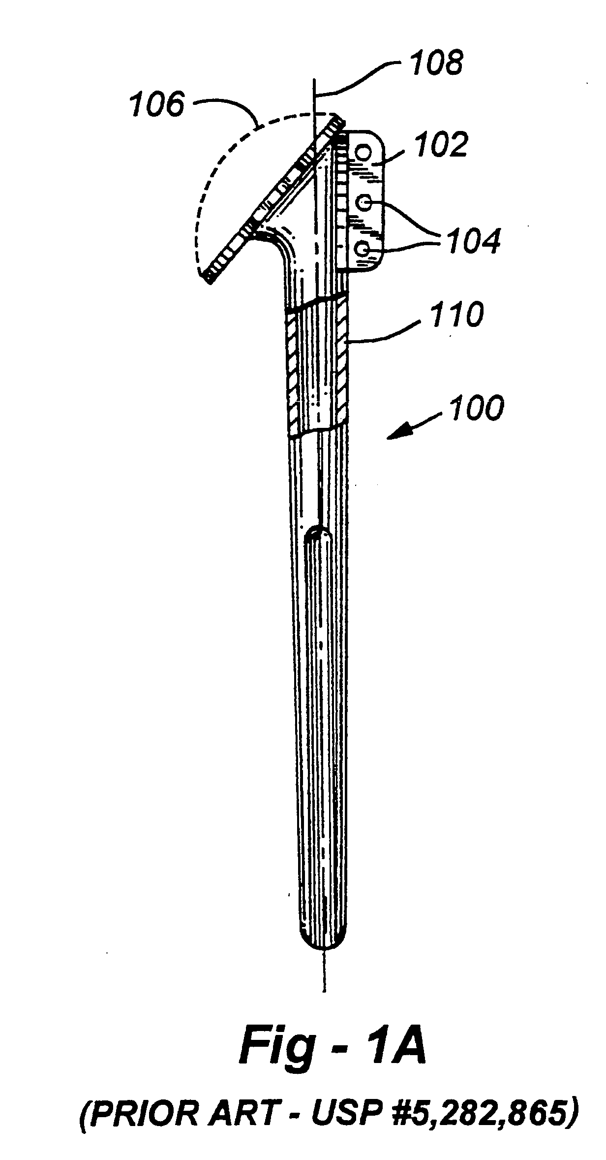
a shoulder and anatomic technology, applied in the field of orthopaedic surgery, can solve the problems of poor fixation in a non-anatomic arrangement, reduced range of motion and strength following the procedure, and vertical orientation tabs such as tab 102 in fig. 1 do not adequately accommodate human anatomy, so as to improve the anatomic attachment area of tendon or bon

Inactive Publication Date: 2005-04-28
MASINI MICHAEL A
View PDF1 Cites 77 Cited by
  • Summary
  • Abstract
  • Description
  • Claims
  • Application Information

AI Technical Summary

Benefits of technology

[0006] The subject invention resides in a humeral prosthesis with improved anatomic attachment areas for tendon or bone. As in prior-art devices, the invention includes an elongated body having a proximal end and a distal end terminating in a stem with an axis configured for placement within an intramedullary canal of a humerus. In the preferred embodiment of the invention, however, and in contrast to existing devices, at least one set of tendon / bone attachment points are provided along a line, at least a portion of which is divergent with respect to the axis of the stem.
[0007] One or more sets of attachment points may further be provided along a line which is substantially parallel to the axis of the stem, resulting in a “T.”“U” or “L” configuration, including inverted versions thereof. Alternatively, attachment points having a changing degree of diversion with respect to the axis of the stem may be provided along a common, curved line. The attachment points may simply be apertures formed through the body of the implant though, in the preferred embodiment, the apertures are provided on raised tabs. An area of bone-ingrowth material may be provided adjacent to or at the attachment site, and may include a separate fastening mechanism such as a threaded hole to receive a screw, or any other alternative means operative to rigidly attach the tendon or bone to the prosthesis. A groove may also be provided in any embodiment to receive the biceps tendon. In addition, a recess may be provided to accept a tendon-bone unit such as the greater or lesser tuberosities with their respective tendons attached. Particularly with respect to fractures, including multi- and ‘four-part’ fractures, means specifically intended for the rigid reattachment of the greater or lesser tuberosities may be provided separately or in conjunction with other sets of reattachment configurations.

Problems solved by technology

Since, in the case of a natural humerus, these tendons attach at different points of the bone to perform specific functions, vertically oriented tabs such as tab 102 in FIG. 1 does not adequately accommodate human anatomy.
This result, being anatomically incorrect, typically results in a reduced range of motion and strength following the procedure, particularly in initiating abduction; that is, in raising that arm.
Re-attachment to a vertical fin with sutures results in poor fixation in a non-anatomic arrangement.

Method used


Image

  • Shoulder prosthesis with anatomic reattachment features
  • Shoulder prosthesis with anatomic reattachment features
  • Shoulder prosthesis with anatomic reattachment features

Examples


Embodiment Construction

[0018] As discussed above, this invention is directed to humeral prostheses providing more anatomical attachment configurations for bone and / or tendons, with the goal being a greater range of post-operative motion and / or strength. Before discussing the various embodiments of the invention in detail, it will be helpful to introduce aspects of the anatomy associated with procedures contemplated herein.

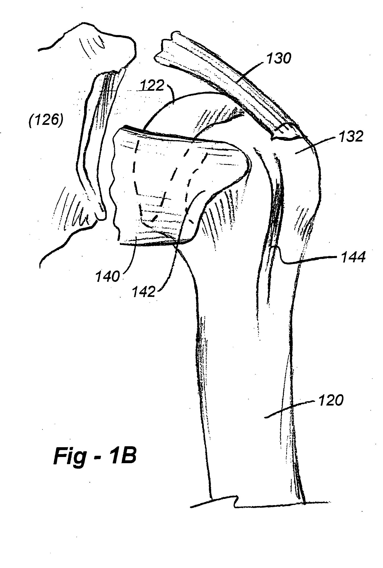
[0019]FIG. 1B is a drawing of a human proximal humerus showing the natural anatomic tendon attachment areas. The humerus, 120, includes a proximal portion having a head 122 with an articulating surface adapted to co-act with the glenoid bone 126 in the shoulder joint. The supraspinatus tendon 130 lies flat on the proximal humerus, and attaches at a section of bone called the greater tuberosity 132. The subscapularis tendon 140 extends across the side of the joint and attaches at the lesser tuberosity 142. A groove 144 receives the biceps tendon (not shown).

[0020]FIG. 1C is a drawing wh...


PUM

PropertyMeasurementUnit
lengthaaaaaaaaaa
strengthaaaaaaaaaa
areaaaaaaaaaaa

Abstract

A humeral prosthesis features improved anatomic attachment areas for tendon or bone. In the preferred embodiment, in contrast to existing devices, at least one set of tendon/bone attachment points are provided along a line, at least a portion of which is divergent with respect to the axis of the stem. One or more sets of attachment points may be further be provided along a line which is substantially parallel to the axis of the stem, resulting in a “T”“L” or “U” shape. Alternatively, attachment points having a changing degree of diversion with respect to the axis of the stem may be provided along a common, curved line. The attachment points may simply be apertures formed through the body of the implant though, in the preferred embodiment, the apertures are provided on raised tabs. An area of bone-ingrowth material may be provided adjacent the attachment points, and may include a separate fastening mechanism such as a threaded hole to receive a screw. A groove may also be provided in any embodiment to receive the biceps tendon. Particularly with respect to fractures, including multi- and ‘four-part’ fractures, means specifically intended for the rigid reattachment of the greater or lesser tuberosities may be provided separately or in conjunction with other sets of reattachment configurations.

Description

FIELD OF THE INVENTION [0001] This invention relates generally to orthopedic surgery and, in particular, to improved shoulder prostheses featuring more anatomic rotator cuff attachment geometries facilitating enhanced fixation of tendon and / or bone. BACKGROUND OF THE INVENTION [0002] A typical proximal humeral prosthesis is depicted generally at 100 in FIG. 1, this particular drawing being taken in part from U.S. Pat. No. 5,282,865. The device includes a modular head attachment 106, though variations of such devices exist, including those without modularity, and designs incorporating different modular arrangements. [0003] A tab 102 is provided on the lateral side of the prosthesis, as shown. The tab 104 is provided with two or more holes 106 disposed parallel to the length of the prosthesis; that is, parallel to the axis 108 of the stem 110. Although the stated purpose of the apertured tab 102 is to assist with installation of the device and to minimize rotation once installed, it i...

Claims


Application Information

Patent Timeline
Patent Type & Authority Applications(United States)
IPC IPC(8): A61B17/06A61F2/00A61F2/08A61F2/30A61F2/40
CPCA61B17/06166A61F2310/00796A61F2/0811A61F2/30767A61F2/30771A61F2/40A61F2/4059A61F2002/30112A61F2002/30131A61F2002/30168A61F2002/30172A61F2002/30332A61F2002/30433A61F2002/30574A61F2002/30578A61F2002/30688A61F2002/30784A61F2002/30797A61F2002/3082A61F2002/30836A61F2002/30884A61F2002/30902A61F2002/4051A61F2002/4062A61F2002/4077A61F2220/0033A61F2220/0041A61F2230/0004A61F2230/0013A61F2230/0043A61F2230/0052A61B17/842
Inventor MASINI, MICHAEL A.
Owner MASINI MICHAEL A
Why Eureka
Try Eureka