
Apparatus and methods for optically inspecting a sample for anomalies

a technology of optical inspection and anomalies, applied in the field of inspection systems, can solve the problems of overloading the detection electronics of instruments, affecting the accuracy of instruments,

Inactive Publication Date: 2005-05-05
KLA TENCOR TECH CORP
View PDF19 Cites 20 Cited by
  • Summary
  • Abstract
  • Description
  • Claims
  • Application Information

AI Technical Summary

Benefits of technology

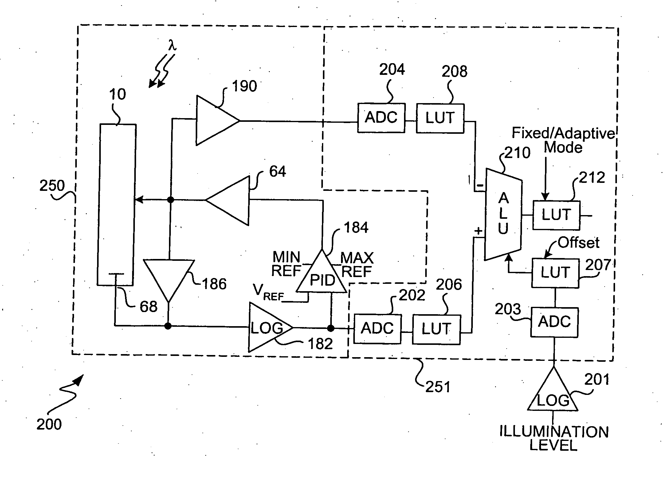
"The patent describes an inspection system that can detect defects on a sample by measuring the intensity of light from a beam that is directed towards the sample. The system has a detector that generates a wide dynamic range of intensity values from the sample. These values are then analyzed to determine if there are any defects present. The system can compensate for variations in intensity levels caused by noise using a normalization function. The system can also include a transformation mechanism to adjust the sensor gain based on the intensity levels and a data processor to determine if there is a defect based on the transformed detected signals. The system can also include an offset mechanism to simulate a programmable sensor gain. Overall, the system provides a reliable and accurate method for detecting defects on semiconductor wafers during the manufacturing process."

Problems solved by technology

Because this dynamic range is substantially greater than the reliable measurement range of existing instruments, inspection operators are forced to accept an unpleasant compromise between inspecting with too low a sensitivity in some portions of the die, and temporarily overloading the instrument's detection electronics in other regions.
However, there is a fundamental trade-off in ADC's between speed and dynamic range.
That is, dynamic range is typically limited by noise and offset errors, both of which tend to increase with speed.

Method used


Image

  • Apparatus and methods for optically inspecting a sample for anomalies
  • Apparatus and methods for optically inspecting a sample for anomalies
  • Apparatus and methods for optically inspecting a sample for anomalies

Examples


Embodiment Construction

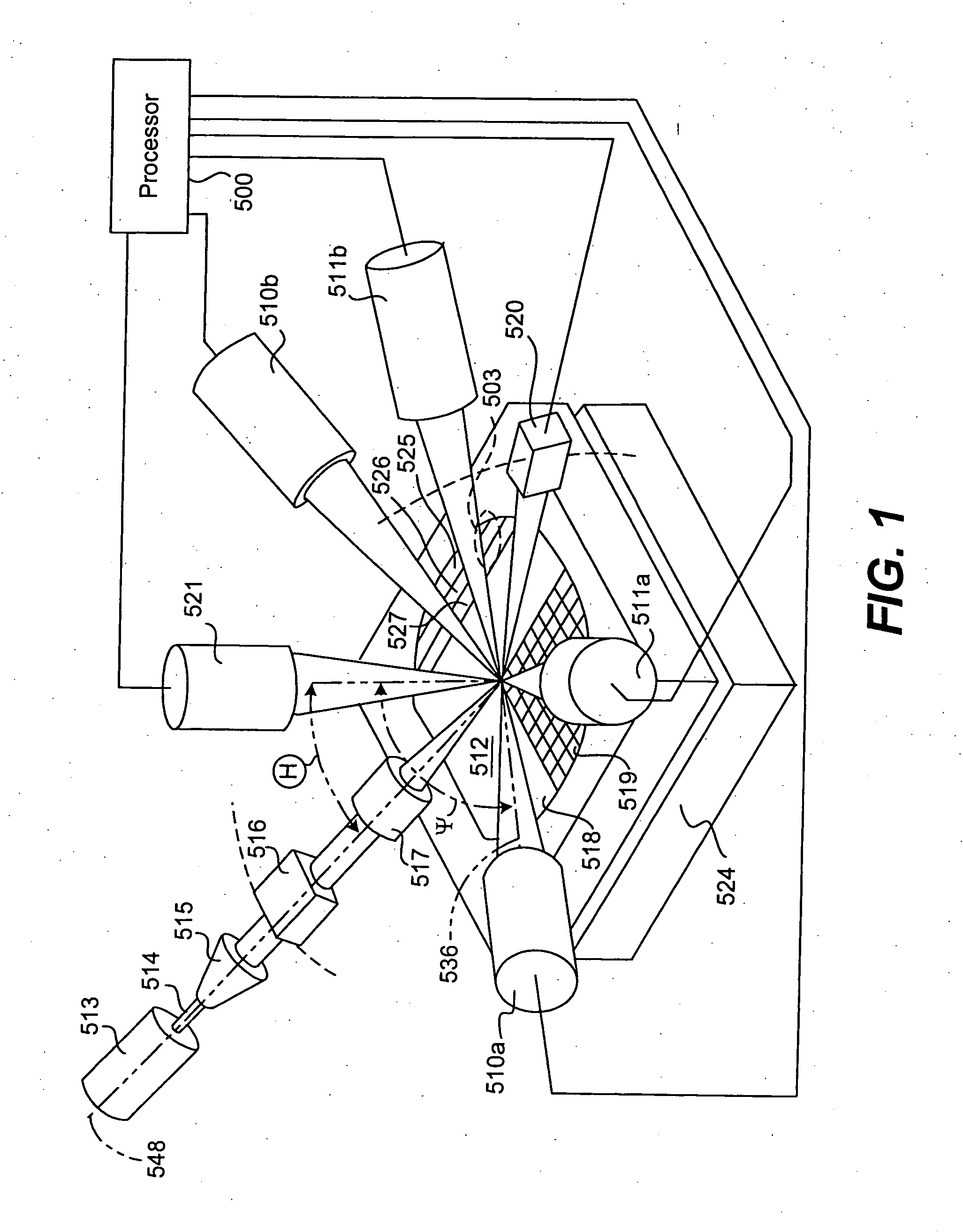
[0040] Reference will now be made in detail to a specific embodiment of the invention. An example of this embodiment is illustrated in the accompanying drawings. While the invention will be described in conjunction with this specific embodiment, it will be understood that it is not intended to limit the invention to one embodiment. On the contrary, it is intended to cover alternatives, modifications, and equivalents as may be included within the spirit and scope of the invention as defined by the appended claims. In the following description, numerous specific details are set forth in order to provide a thorough understanding of the present invention. The present invention may be practiced without some or all of these specific details. In other instances, well known process operations have not been described in detail in order not to unnecessarily obscure the present invention.

[0041] In general terms, the inspection systems of the present invention is capable of detecting a relativ...


PUM

PropertyMeasurementUnit
wavelengthaaaaaaaaaa
angleaaaaaaaaaa
azimuthal angle ψ1aaaaaaaaaa

Abstract

Disclosed are methods and apparatus for detecting a relatively wide dynamic range of intensity values from a beam (e.g., scattered light, reflected light, or secondary electrons) originating from a sample, such as a semiconductor wafer. In other words, the inspection system provides detected output signals having wide dynamic ranges. The detected output signals may then be analyzed to determine whether defects are present on the sample. For example, the intensity values from a target die are compared to the intensity values from a corresponding portion of a reference die, where a significant intensity difference may be defined as a defect. In a specific embodiment, an inspection system for detecting defects on a sample is disclosed. The system includes a beam generator for directing an incident beam towards a sample surface and a detector positioned to detect a detected beam originating from the sample surface in response to the incident beam. The detector has a sensor for detecting the detected beam and generating a detected signal based on the detected beam and a non-linear component coupled to the sensor. The non-linear component is arranged to generate a non-linear detected signal based on the detected signal. The detector further includes a first analog-to-digital converter (ADC) coupled to the non-linear component. The first ADC is arranged to digitize the non-linear detected signal into a digitized detected signal.

Description

CROSS REFERENCE TO RELATED APPLICATIONS [0001] This application claims priority of co-pending U.S. patent application Ser. No. 10 / 180,807 (Attorney Docket No. KLA1P075), filed 24 Jun. 2002 by Ralph C. Wolf et al, which claims priority of U.S. Provisional Patent Application No. 60 / 359,805 (Attorney Docket No. KLA1P075P), filed 26 Feb. 2002 by Ralph C. Wolf et al., which application is incorporated herein by reference in its entirety for all purposes.BACKGROUND OF THE INVENTION [0002] The present invention relates generally to inspection systems. More specifically, it relates to light collection mechanisms for inspecting semiconductor wafers and other types of patterned samples. [0003] Conventional darkfield optical inspection tools locate defects on patterned wafers by scanning the surface of the wafer with a tightly focused laser spot and measuring the amount of light scattered by the illuminated spot on the wafer. Dissimilarities in the scattering intensity between similar location...

Claims


Application Information

Patent Timeline
Patent Type & Authority Applications(United States)
IPC IPC(8): G01N21/47G01N21/88G01B11/30G01N21/95G01N21/956
CPCG01N21/47G01N21/956G01N21/9501
Inventor WOLF, RALPH C.BENITEZ, EVA L.GREENE, JOHN D.SULLIVAN, JAMIE M.VELLA, ERIC N.VO, KHIEM D.
Owner KLA TENCOR TECH CORP
Learn More