Indicating instrument

a technology of indicating instruments and circuit components, applied in the direction of instruments, motors/generators/converter stoppers, dynamo-electric converter control, etc., can solve the problems of large number of circuit components and complex control

Inactive Publication Date: 2005-05-05
CALSONIC KANSEI CORP
View PDF18 Cites 4 Cited by
  • Summary
  • Abstract
  • Description
  • Claims
  • Application Information

AI Technical Summary

Benefits of technology

[0008] The present invention has been made in view of the above-mentioned problems. Therefore, it is an object of the present invention to provide an indicating instrument in which circuits for detecting induced voltage and carrying out zero-reset judgment on the basis of the induced voltage are simplified.
[0009] To accomplish the above mentioned object, an indicating instrument according to a first aspect of the present invention comprises: a stepping motor having a magnet rotor and a stator provided with two field windings for rotating the magnet rotor; a PWM signal generating device for generating respective PWM signals of an artificial sine-wave and an artificial cosine-wave which are supplied to each of the field windings for rotating the magnet rotor; a pointer rotated in accordance with rotation of the magnet rotor; and a stopper mechanism for stopping rotation of the pointer when the pointer has returned to a zero-reset position, wherein the indicating instrument further comprises: an output port open control device for controlling an output port which outputs the PWM signals to either end of one of the field windings to be in an open state during a period in which the PWM signals supplied to the one of the field windings are in a ground level, at the time when the pointer is rotated to a zero-reset direction by supplying the respective PWM signals which are for rotating the pointer toward the zero-reset direction to each of the field windings; a voltage comparator for comparing magnitude of induced voltage induced in the one of the field windings and previously set threshold value voltage and generating an binary output; and a zero-reset judging device for judging whether the pointer is in the middle of the rotation or the pointer is in contact with the stopper mechanism and the rotation of the pointer is stopped, based on the binary output of the voltage comparator in a period in which the output port is controlled to be in the open state.
[0010] An indicating instrument according to a second aspect of the present invention comprises: a stepping motor having a magnet rotor and a stator provided with two field windings for rotating the magnet rotor; a PWM signal generating device for generating respective PWM signals of an artificial sine-wave and an artificial cosine-wave which are supplied to each of the field windings for rotating the magnet rotor; a pointer rotated in accordance with rotation of the magnet rotor; and a stopper mechanism for stopping rotation of the pointer when the pointer has returned to a zero-reset position, wherein the indicating instrument further comprises: an output port selecting / open connection control device for controlling an output port which outputs the PWM signals to either end of one of the field windings to be in an open state during a period in which the PWM signals supplied to the one of the field windings are in a ground level, and carrying out control in which the field windings of the output port are selectively connected to an induced voltage detecting circuit, at the time when the pointer is rotated to a zero-reset direction by supplying the respective PWM signals which are for rotating the pointer toward the zero-reset direction to each of the field windings; a selector for connecting the field winding selected by the output port selecting / open connection control device with the induced voltage detecting circuit; a voltage comparator provided in the induced voltage detecting circuit for comparing magnitude of induced voltage induced in the one of the field windings and previously set threshold value voltage and generating an binary output; and a zero-reset judging device for judging whether the pointer is in the middle of the rotation or the pointer is in contact with the stopper mechanism and the rotation of the pointer is stopped, based on the binary output of the voltage comparator in a period in which the output port is controlled to be in the open state.

Problems solved by technology

Therefore, there have been problems that the number of circuit component is large and control becomes complicated.

Method used


Image

  • Indicating instrument
  • Indicating instrument
  • Indicating instrument

Examples


first embodiment

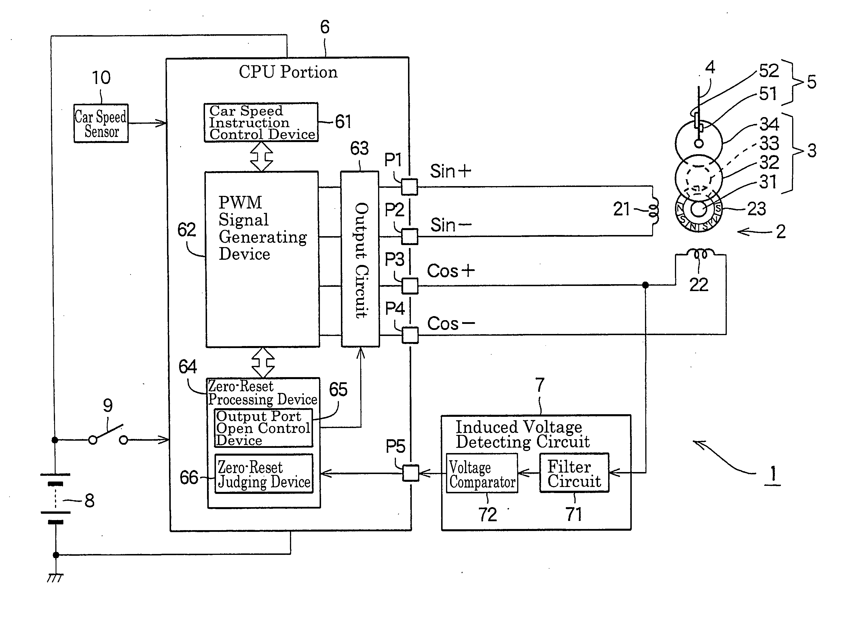
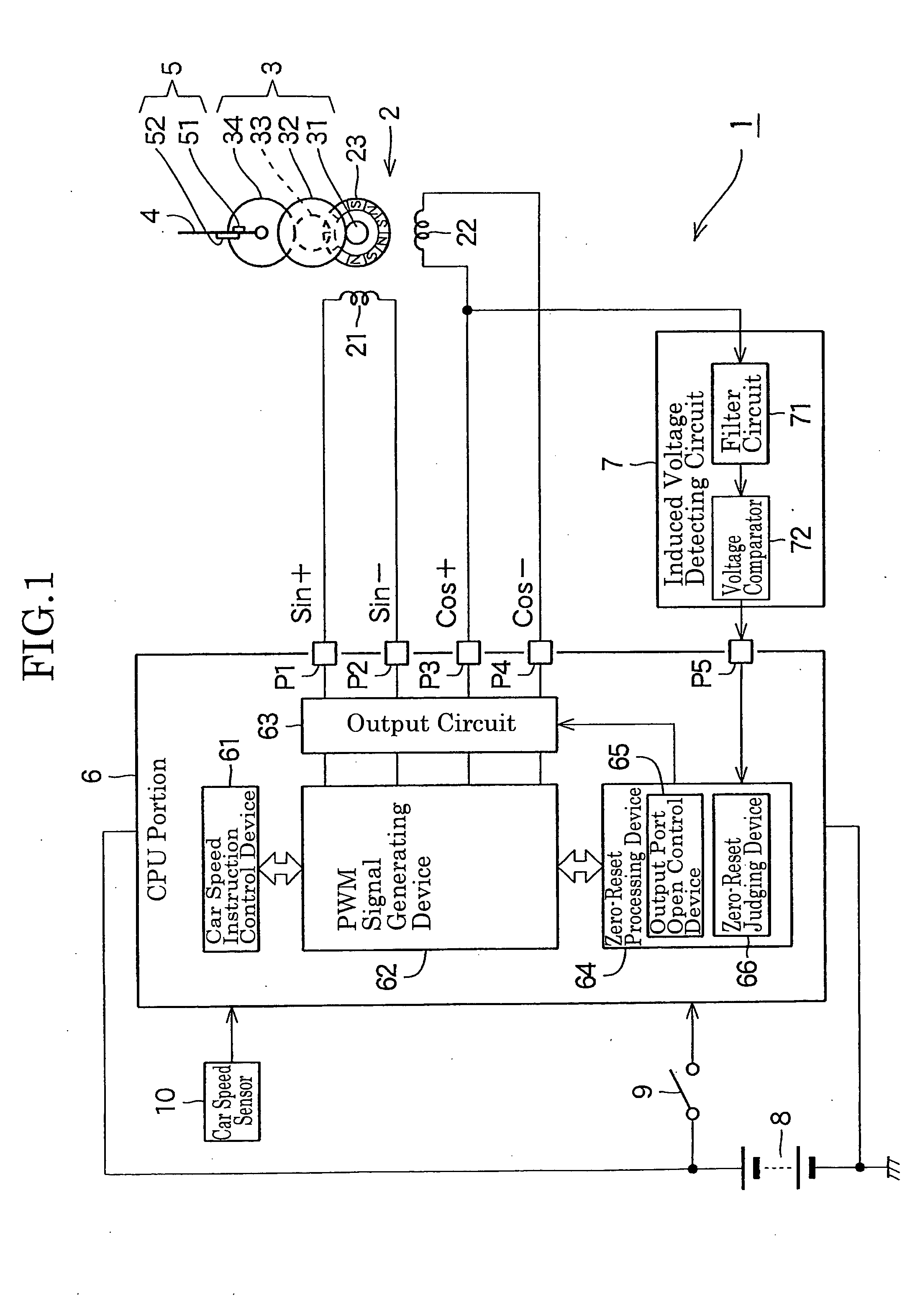
[0020]FIG. 1 is a diagram showing a frame format structure and a block structure of an indicating instrument according to a first embodiment of the present invention.

[0021] In the first embodiment, explanation on a speedometer (car speed meter) for a vehicle will be given as an indicating instrument. The indicating instrument 1 comprises a two-phase type stepping motor 2, a pointer 4 rotated through a reduction gear mechanism 3, a stopper mechanism 5 for stopping the rotation of the pointer 4, a CPU portion 6, and an induced voltage detecting circuit 7. The indicating instrument 1 is operated by receiving supply of power from a battery 8. The CPU portion 6 includes a power supply circuit or the like. The CPU portion 6 drives the stepping motor 2 based on an output of detection of a car speed sensor 10 when an ignition switch 9 is in an ON state, to rotate the pointer 4 to a position on a scale of a not-shown dial plate corresponding to a car speed.

[0022] The stepping motor 2 is pr...

second embodiment

[0045]FIG. 6 shows an indicating instrument 101 according to the second embodiment of the present invention. Meanwhile, portions in the present embodiment, which are same or equivalent to the indicating instrument 1 of the first embodiment, will be explained by attaching same reference numerals used therein.

[0046] First, to explain mainly on structural differences, an output circuit 163 of the indicating instrument 101 according to the second embodiment includes switch circuits T1 to T4 in which a switching element such as the transistor for outputting the voltage of the “high” level (power supply voltage level) and a switching element such as the transistor for outputting the voltage of the “ground” level are connected in series with the power source, are provided corresponding to each of the output ports P1 to P4, respectively. The output circuit 163 is capable of allowing the output ports P1 to P4 to be in the open (high impedance) state, individually, by driving each of the swi...


PUM


Abstract

An output port open control device (65) allows a port (P3) which outputs PWM signals of a Cos+ side to be in a high impedance state in a period in which respective PWM signals of Cos+ and Cos− supplied to a S-phase coil (22) of a stepping motor (2) are in a ground level, induced voltage corresponding to a magnetic flux variation caused in accordance with rotation of a magnet rotor (23) is generated in the S-phase coil (22), a voltage comparator (72) compares the induced voltage with a previously set threshold value and outputs presence or absence of the induced voltage, and a zero-reset judging device (66) determines that a pointer (4) is in the middle of rotation when the induced voltage is detected, and determines that the pointer (4) is in contact with a stopper mechanism (5) when it is not detected.

Description

BACKGROUND OF THE INVENTION [0001] 1. Field of the Invention [0002] The present invention relates to an indicating instrument which uses a stepping motor as a primary drive of a pointer. [0003] 2. Description of the Related Art [0004] In an indicating instrument in which a stepping motor is used as a primary drive of a pointer, a reference position of the pointer is set by rotating the pointer toward a zero-reset position and stopping the pointer at the zero-reset position with a stopper mechanism, in order to carry out a step-out reset. [0005] Induced voltage is generated in a field winding during when the pointer moves, i.e., when a magnet rotor of the stepping motor rotates. The induced voltage will not be generated in the field winding if the pointer stops at the zero-reset position and the rotation of the magnet rotor is stopped. [0006] Given this factor, the field winding of the stepping motor is switched to a non-excited state during the course of driving the stepping motor w...

Claims


Application Information

Patent Timeline
Patent Type & Authority Applications(United States)
IPC IPC(8): G01D11/00G01D7/00G01D11/16G01D13/22G01R7/06H02P8/28
CPCG01D7/00G01R7/06G01D13/22G01D11/16G01D2213/10
Inventor SASAKI, KIYOSHI
Owner CALSONIC KANSEI CORP
Why Eureka
Try Eureka