
Controlling a telescopic antenna mast

a technology of telescopic antennas and masts, which is applied in the direction of collapsable antennas, resonant antennas, elongated active element feeds, etc., can solve the problems of limited height of masts, limited maximum range of effective communications, and limited propagation of electromagnetic radiation in microwave frequency ranges

Active Publication Date: 2005-05-05
DEERE & CO
View PDF5 Cites 215 Cited by
  • Summary
  • Abstract
  • Description
  • Claims
  • Application Information

AI Technical Summary

Benefits of technology

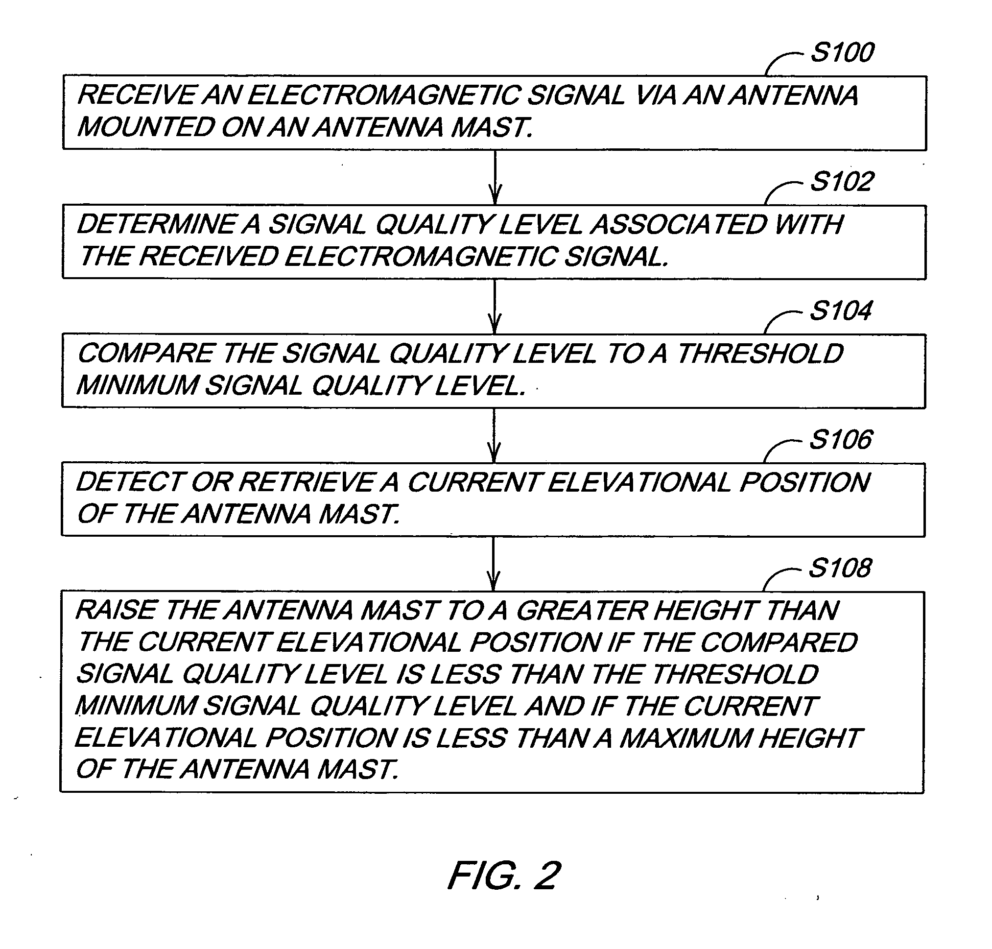
[0003] A receiver receives an electromagnetic signal via an antenna mounted on an antenna mast. A signal evaluator measures or determines a signal quality level associated with the received electromagnetic signal. The signal evaluator compares the measured signal quality level to a threshold minimum signal quality level. A current

Problems solved by technology

The mast may be limited in height because of obstructions in the environment.
The limitation in height of the antenna may limit the maximum range of effective communications between the vehicle and a communications device located remotely apart from the vehicle.
For example, electromagnetic radiation that is in the microwave frequency range may be limited to propagation in line-of-sight paths or may be severely attenuated by ground clutter where antenna height is insufficient for a requisite level of clearance.

Method used


Image

  • Controlling a telescopic antenna mast
  • Controlling a telescopic antenna mast
  • Controlling a telescopic antenna mast

Examples


Embodiment Construction

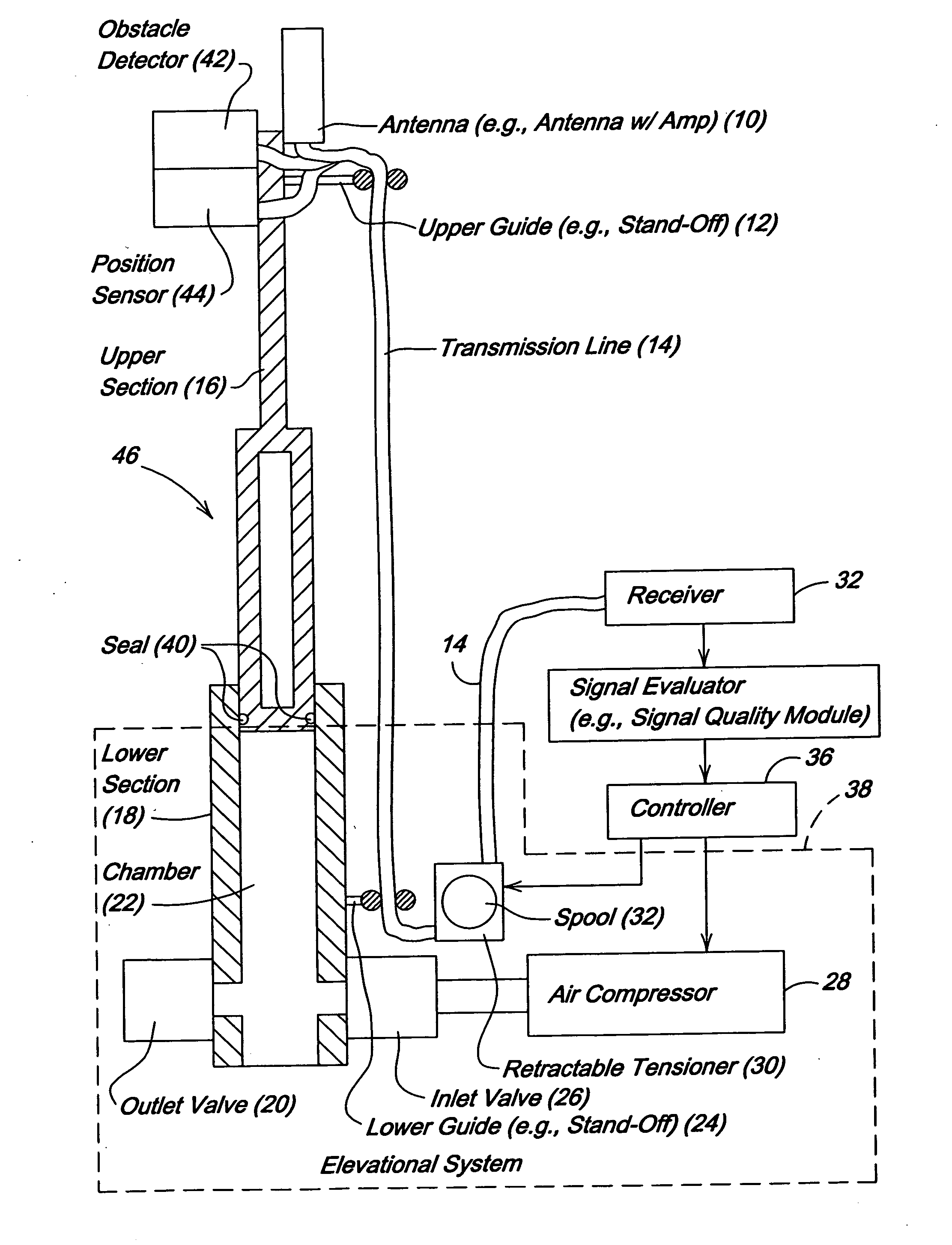
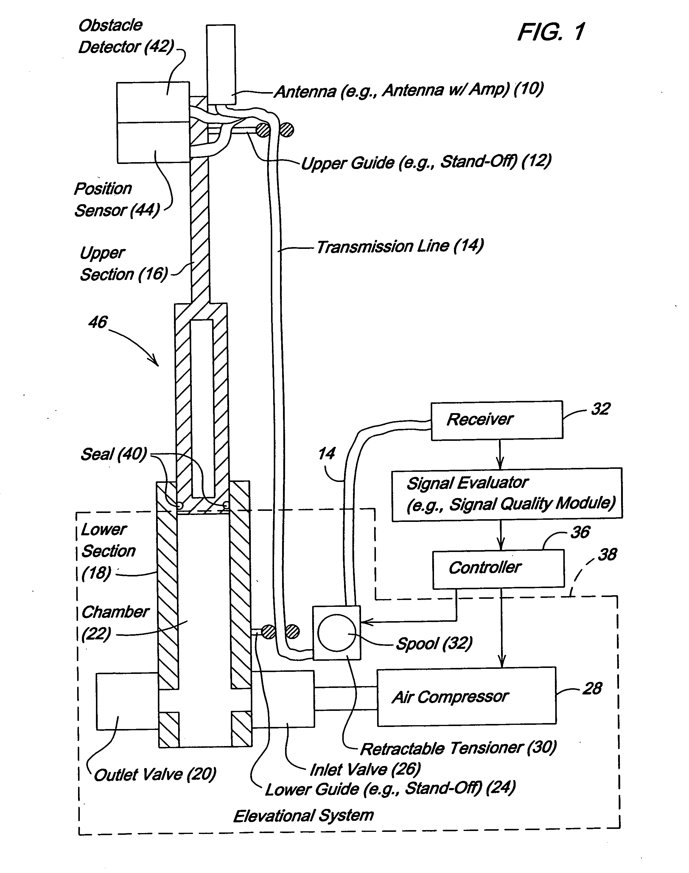
[0008]FIG. 1 illustrates an antenna mast assembly and a system for controlling an elevation of the antenna mast 46 to enhance communications between an antenna 10 mounted on the antenna mast 46 and another communications device spatially separated from the antenna 10.

[0009] The antenna mast assembly comprises an antenna mast 46, an antenna 10 mounted thereon, transmission line 14 coupled to the antenna 10, and one or more transmission line guides (12, 24) for supporting the transmission line 14. The antenna mast 46 includes multiple sections. For example, the antenna mast 46 includes at least a first section (e.g., upper section 16) and a second section (e.g., lower section 18). Each section may have a generally circular, elliptical, triangular, rectangular cross section or a cross section of another shape that interlocks or slidably engages at least one adjacent section. Although the antenna mast 46 may be of virtually any height that can be carried by a vehicle and supported stab...


PUM


Abstract

A receiver receives an electromagnetic signal via an antenna mounted on an antenna mast. A signal evaluator determines or measures a signal quality level associated with the received electromagnetic signal. The signal quality compares the determined signal quality level to a threshold minimum signal quality level. A current elevational position of the antenna mast is detected or tracked. The antenna mast is raised to a greater height than the current elevational position if the compared signal quality level is less than the threshold minimum signal quality level and if the current elevational position is less than a maximum height of the antenna mast.

Description

FIELD OF THE INVENTION [0001] This invention relates to a method and system of controlling a telescopic antenna mast. BACKGROUND OF THE INVENTION [0002] An antenna mast may be mounted on a vehicle to support the mounting of antenna. The antenna may be used for reception, transmission or both reception and transmission of an electromagnetic signal. The mast may be limited in height because of obstructions in the environment. Obstructions may include vegetation, vine canopies, tree canopies, bridges, traffic signals, buildings or otherwise. The limitation in height of the antenna may limit the maximum range of effective communications between the vehicle and a communications device located remotely apart from the vehicle. For example, electromagnetic radiation that is in the microwave frequency range may be limited to propagation in line-of-sight paths or may be severely attenuated by ground clutter where antenna height is insufficient for a requisite level of clearance. Accordingly, ...

Claims


Application Information

Patent Timeline
IPC IPC(8): H01Q1/12H01Q1/32H01Q9/30H04B1/04H04B1/18
CPCH01Q1/1235
Inventor TURNER, CHRISTOPHER DAVID GLENN
Owner DEERE & CO
Learn More