Vehicle transmission system with coast controls

a transmission system and coast control technology, applied in mechanical equipment, transportation and packaging, instruments, etc., can solve the problems of not being addressed, engine speed may be increased and the clutch engaged, and surge in the drivetrain, etc., to achieve more efficient transmission control

Active Publication Date: 2005-05-05
ZF MERITOR L L C
View PDF12 Cites 10 Cited by
  • Summary
  • Abstract
  • Description
  • Claims
  • Application Information

AI Technical Summary

Benefits of technology

[0010] Thus, the subject invention provides more efficient transmission control during coast starts. These and other features of the present invention can be best understood from the following specification and drawings, the following of which is a brief description.

Problems solved by technology

One problem that has not been addressed relates to vehicles experiencing a coast start.
Thus, the engine speed may be increased and the clutch engaged during unfavorable conditions.
This is undesirable because due to the sudden closure or engagement of the clutch, there is a surge in the drivetrain.
This can cause overloading or shock loading of certain drivetrain components, resulting in premature wear or failure.
Another problem with coast starting concerns gear ratios.
The transmission system does not adjust the transmission gear ratio in response to a coast start.
This can result in a harsh or abrupt transition as the clutch is moved into the engaged position, causing discomfort to vehicle occupants.

Method used


Image

  • Vehicle transmission system with coast controls
  • Vehicle transmission system with coast controls

Examples


Embodiment Construction

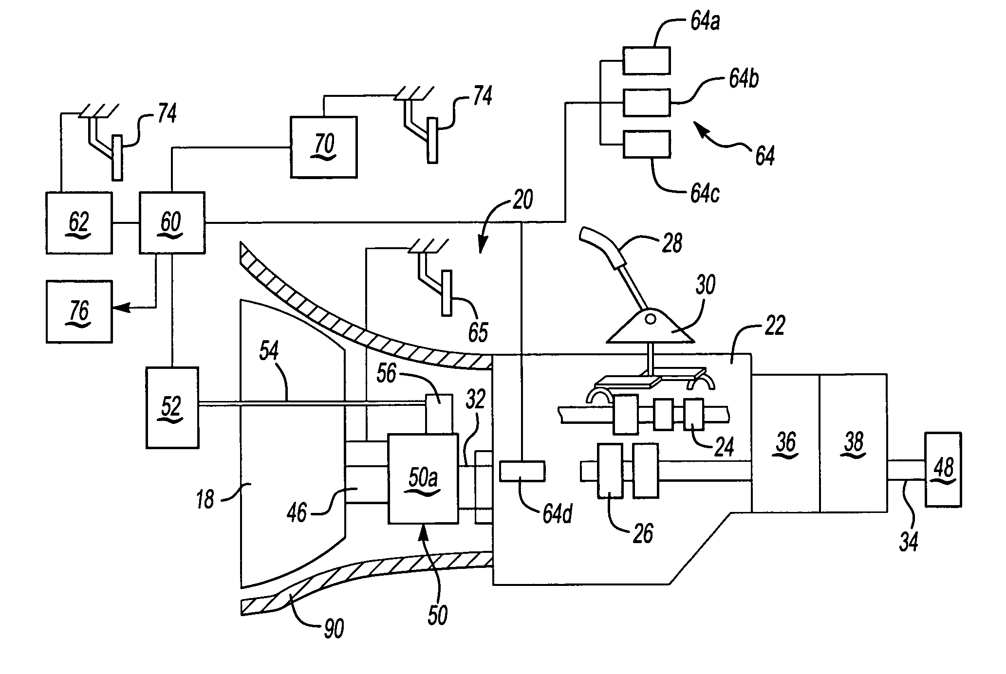
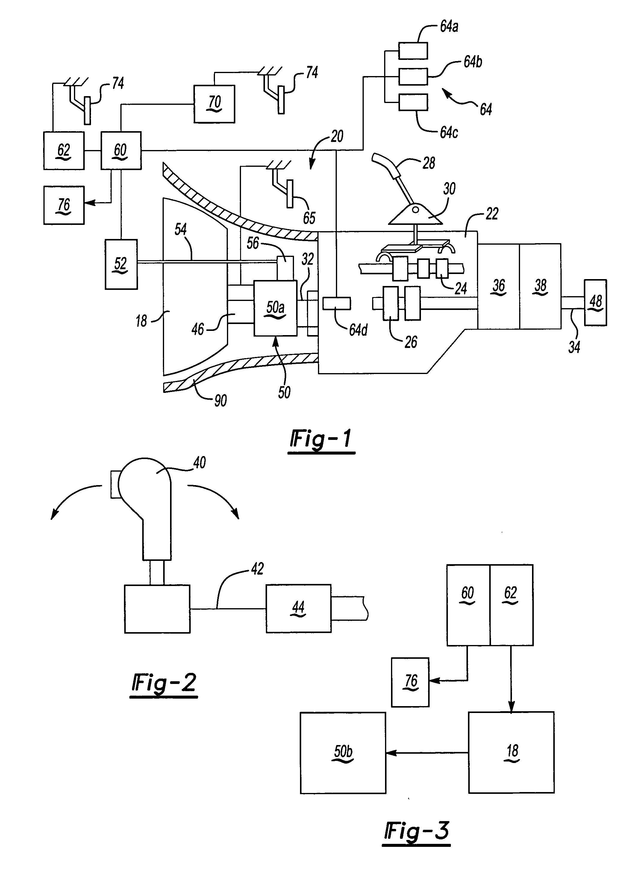
[0014]FIG. 1 diagrammatically illustrates an engine 18 and a transmission system 20 including a main gear box 22 that has a plurality of gear members 24 and 26. In the illustrated embodiment, a manually operable shift lever 28 is moveable about a pivot point 30 to manually, selectively engage one of the gear members 24 and 26 to achieve a desired gear ratio between a transmission input shaft 32 and a transmission output shaft 34.

[0015] The transmission system 20 can include a splitter gear assembly 36 to provide additional gear ratios between the ratios provided by gear members 24, 26 in the main gear box 22, or a range gear box 38 to provide additional gear ratios greater than the ratios provided by gear members 24, 26. The operation of range gear boxes 38 and splitter assemblies 36 are well known in the art and will not be discussed in detail. In some instances the use of a range gear box 38 or a splitter assembly 36 may not be necessary.

[0016] Additionally (as schematically ill...


PUM


Abstract

A vehicle transmission system includes a transmission component that has an engaged condition where torque can be transferred from a vehicle engine to a drive component, and a non-engaged condition where torque is prohibited from being transferred to the drive component. A controller generates control signals to control whether the transmission component is in the engaged or non-engaged condition. The controller also identifies when a vehicle start maneuver is a coast start based on vehicle conditions existing just prior to or during the vehicle start maneuver. When a coast start is identified, the controller generates a control signal to either disengage the transmission component or to maintain the transmission component in the non-engaged condition until engine speed generally matches transmission component speed. The controller can directly control engagement by automatically actuating a movable transmission member or can indirectly control engagement by controlling engine speed. Once engine speed and transmission component speed are generally within a common speed range during coasting, the transmission component is engaged.

Description

BACKGROUND OF THE INVENTION [0001] This application generally relates to vehicle transmissions. More particularly, this invention relates to a transmission system that predicts and identifies coast starts, and which directly or indirectly controls clutch operation under coast conditions. [0002] A variety of vehicle transmissions are available currently in the market. Some transmissions are automated and do not require operator input other than selecting a gear mode, for example, reverse or drive. Other transmissions are manual and require manual operation of a gear shift lever to manually move transmission components into selected gear ratios. Manual transmissions typically require manual actuation of a clutch pedal to eliminate the connection between an engine output shaft and an input shaft of the transmission. Manual clutch pedal actuation is typically required each time that a shift in gears is desired. [0003] More recently, suppliers and vehicle manufactures have been attemptin...

Claims


Application Information

Patent Timeline
Patent Type & Authority Applications(United States)
IPC IPC(8): B60W10/02B60W10/06B60W30/18F16H61/00F16H61/16F16H63/50
CPCB60K2741/283Y10T477/638B60W10/02B60W10/06B60W30/186B60W2510/0638B60W2510/1015B60W2520/10B60W2550/142F16H61/16F16H63/50F16H2306/54F16H2059/663F16H2059/186Y10T477/753Y10T477/78Y10T477/69B60K2741/286B60W10/10B60W2552/15B60W30/18027
Inventor DEVORE, JAMES H.ALLEN, CHARLES E. JR.STURMER, WINFRIEDHEINZELMANN, KARL-FRITZRONGE, LUDGERDREIER, LOREN C.SAYMAN, ROBERT A.MUETZEL, RONALD P.ABUSAMRA, MUNEER
Owner ZF MERITOR L L C
Why Eureka
Try Eureka