
Method and apparatus for transplanting a hair graft

a technology for hair grafts and apparatuses, applied in the field of apparatus and methods for transplanting hair grafts, can solve the problems of very delicate and sensitive controls of instruments, the transplant process,

Active Publication Date: 2005-05-05
RASSMAN WILLIAM R
View PDF9 Cites 41 Cited by
  • Summary
  • Abstract
  • Description
  • Claims
  • Application Information

AI Technical Summary

Benefits of technology

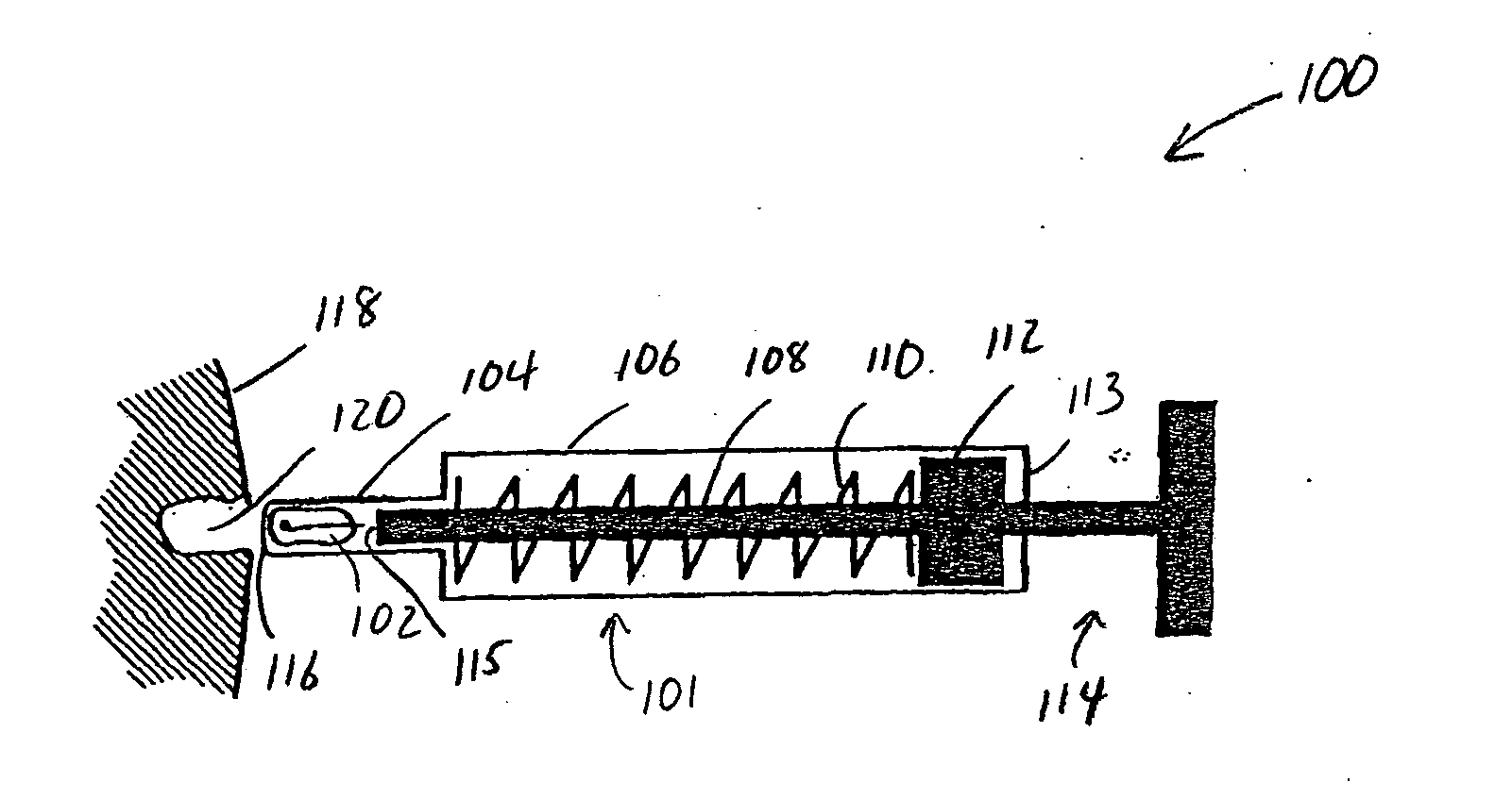
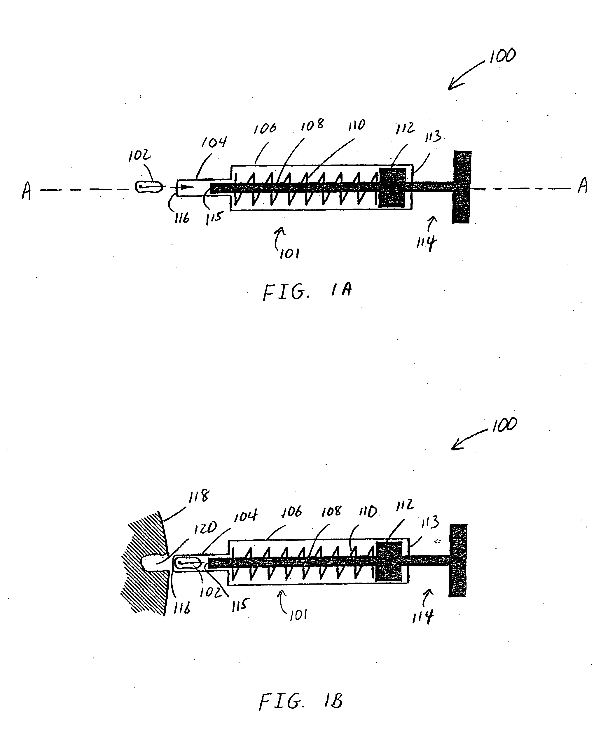
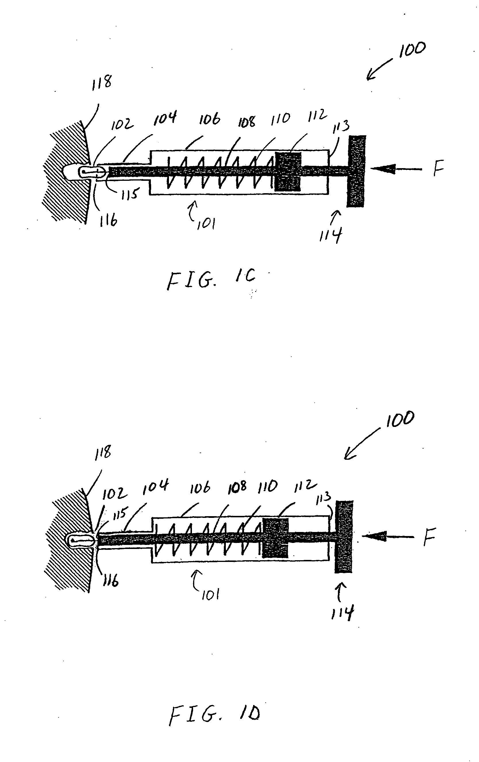
[0014] According to yet another embodiment of the present invention, a method for transplanting a hair graft is provided, including providing a housing having an open distal end, and providing a gas-permeable rod inside the housing, an end of the rod being movable between a first position and a second position along a central axis of the housing. The method further includes providing a spacing between the end of the rod and the open distal end of the housing, providing a vacuum inside the housing to load a hair graft into the spacing, and moving the end of the rod substantially flush with the open distal end of the housing thereby moving the hair graft out of the spacing and into a scalp wound without the open distal end of the housing penetrating the scalp wound.

Problems solved by technology

Current techniques for hair transplantation limits the transplant process to creating follicular units that contain one to four hairs bunched together as they are found in a normal human scalp and using these follicular units as hair grafts.
Usually, the instrument has very delicate and sensitive controls and requires fine adjustments to position the needle tip to capture a graft.

Method used


Image

  • Method and apparatus for transplanting a hair graft
  • Method and apparatus for transplanting a hair graft
  • Method and apparatus for transplanting a hair graft

Examples


Embodiment Construction

[0029] In conventional hair graft transplanting instruments, a needle is in part or in whole inserted through the skin or the skin edge of a wound to a depth approximately equal to the length of a human hair follicular unit. These instruments guide the hair to its final resting position through a mechanical process where a part of the transplant instrument (e.g., a finger projection or a needle type housing) holds the graft as that part of the instrument is inserted to its ideal depth before the graft is expelled from the instrument. The part of the instrument that goes below the skin edge adds bulk to the space where the hair graft is being placed. The mechanical action of the instrument as it implants a graft places pressure on the skin, whether or not it is cutting though the skin, and also increases the volume and pressure within the space intended only for the hair graft.

[0030] The changes in the wound environment at or below the point where the graft is to be inserted is dyna...


PUM


Abstract

A hair transplant apparatus and method capture a hair graft into a hair graft chamber readily aligned for implantation into the human scalp. The hair graft can be placed into the hair graft chamber manually or mechanically (e.g., by vacuum). A hair transplant apparatus includes a gas-permeable stopper for utilizing gas flow to load and / or implant a hair graft. Another hair transplant apparatus includes a gas-permeable rod inside a housing. Vacuum may be utilized to load a hair graft into the hair graft chamber. The rod may be advanced toward an open distal end of the chamber so the end of the rod becomes substantially flush with the distal end, thereby pushing the hair graft out of the chamber and into the pre-made wound. Advantageously, the chamber is aligned with the direction of the pre-made wound allowing the hair graft to slide easily into the pre-made wound without damage. Extraneous forces are eliminated by the alignment of the chamber to the wound, thus creating a linear path for the hair graft to move without obstruction to finally settle in the scalp wound.

Description

BACKGROUND OF THE INVENTION [0001] 1. Field of Invention [0002] This invention relates to an apparatus and method for transplanting hair grafts, and more particularly, to an apparatus and method for non-invasively implanting hair grafts into pre-made wounds. [0003] 2. Discussion of the Related Art [0004] The transplantation of hair grafts into a human scalp is well understood. The present state of the art calls for excising a hair-rich area of the scalp, dissecting the excised scalp segment to obtain individual hair grafts for implantation, creating an implantation site in a bald or thinning area of the scalp by making wounds with a cutting instrument, and then implanting individual grafts into the prepared implantation sites after bleeding has ceased. [0005] Current techniques for hair transplantation limits the transplant process to creating follicular units that contain one to four hairs bunched together as they are found in a normal human scalp and using these follicular units a...

Claims


Application Information

Patent Timeline
IPC IPC(8): A61B17/00A61B17/34A61F2/10
CPCA61B17/3468A61F2/10A61B2017/00969A61B2017/00752
Inventor RASSMAN, WILLIAM R.PAK, JAE P.
Owner RASSMAN WILLIAM R
Learn More