Non-polluting high temperature combustion system

a combustion system and high temperature technology, applied in the field of closed combustion systems, to achieve the effect of efficient disposal

a combustion system and high temperature technology, applied in the field of closed combustion systems, to achieve the effect of efficient disposal

US20050098073A1Inactive Publication Date: 2005-05-12CARTER JR GREG +1

Image

  • Non-polluting high temperature combustion system
  • Non-polluting high temperature combustion system
  • Non-polluting high temperature combustion system

Examples


Embodiment Construction

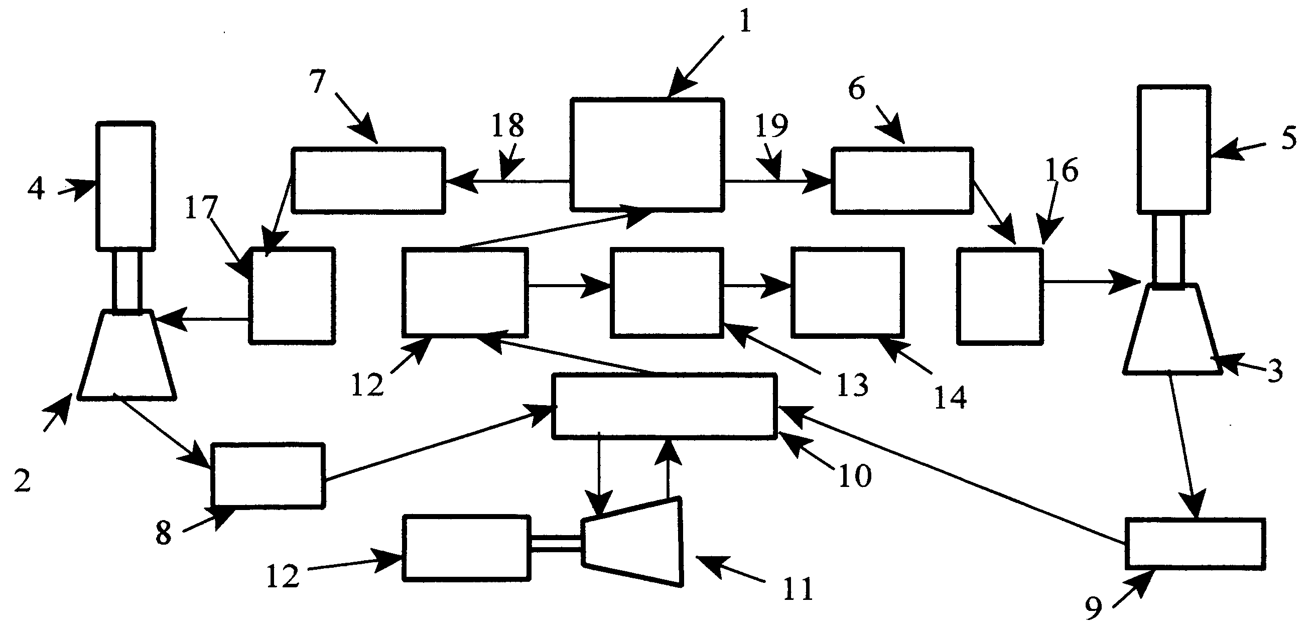
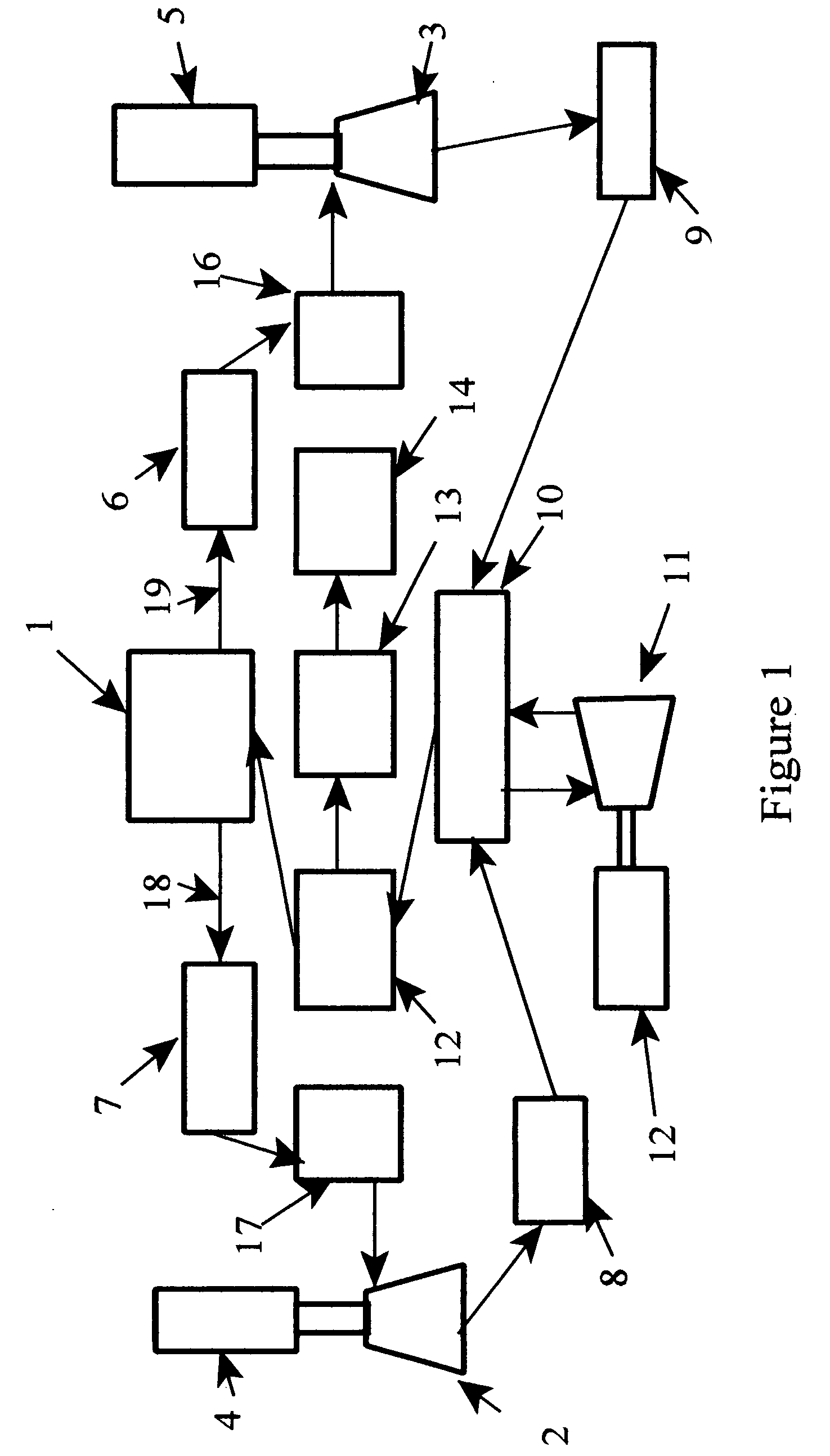
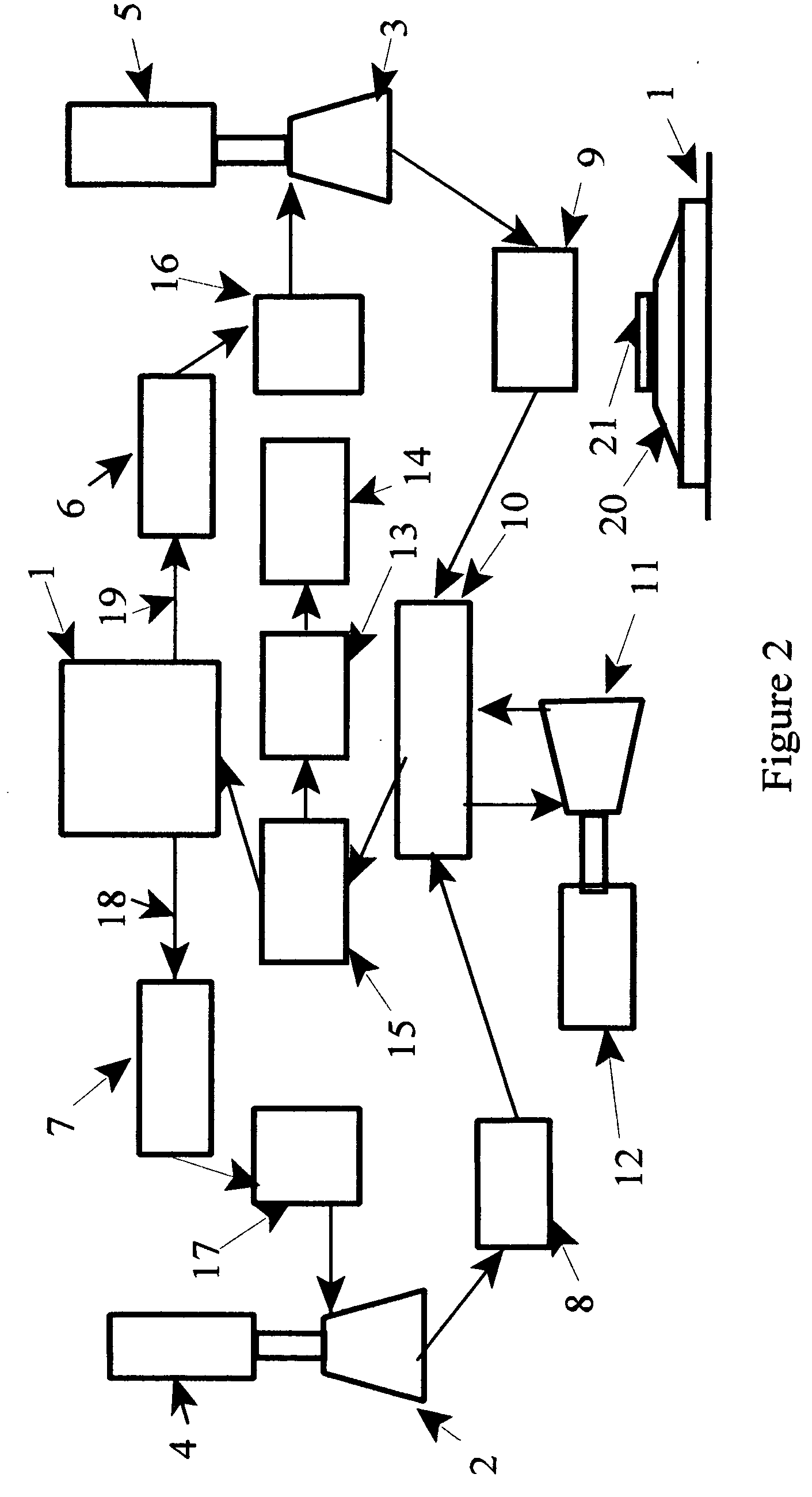
[0010] According to Applicants' invention a combustion system for industrial processes is provided that reaches high temperatures. By “high temperatures” it is meant up to 6000 degrees Fahrenheit, preferably between 2500 and 6000 degrees Fahrenheit, even more preferably 3400 degrees Fahrenheit. By “industrial processes” it is meant high volume processes subject to emit pollutants above the governmental level. Industrial processes include incineration of municipal waste and other waste and hazardous materials, power plant processes, processes for treatment of metals, production of cement, glass and other products and the like. The system is provided with a fuel that burns with a temperature up to 6000 degrees Fahrenheit. Thermite compositions are very well known and consist generally of a mixture of a finely divided, strongly reducible metal oxide, and a finely divided strong reducing agent, typically consisting of aluminum. Once ignited, the composition reacts highly exothermically ...


PUM


Abstract

Disclosed is a non-polluting high temperature combustion system which comprises in combination a graphite-lined combustion chamber fueled by a controlled-burn thermite fuel, wherein the fuel burns a temperature of up to 6000 degrees Fahrenheit, wherein the resulting gases are essentially pollution free; the system also include a means of passing a substrate into and out of the combustion chamber and / or a turbine powered by gases from the combustion products, means of injecting a working fluid into the combustion gases upstream of the turbine, a heat recovery means that comprises a geo-thermal hot rock bed, a steam generator utilizing heat from the geo-thermal hot rock bed, a working fluid separation means which comprises a condenser, and means of liquefying the remaining gases for commercial use.

Description

FIELD OF THE INVENTION [0001] This invention relates to combustion systems that can apply to applications that can tolerate high temperatures, more particularly this invention relates to closed combustion systems that minimize or eliminate pollution, even more particularly this invention relates to closed combustion systems that can apply to applications that can tolerate temperatures between 2500 and 6000 degrees Fahrenheit and minimize or eliminate pollution. BACKGROUND OF THE INVENTION [0002] In combustion systems which generate heat for industry, power plants, incineration of waste, and the like, fuels such as natural gas, coal, fuel oil, and other fuels are used. To produce the heat from these combustion systems, these fuels are typically burned in compressed air or oxygen enriched compressed air or substantially pure oxygen obtained by gas separation. Because of conservation concerns and the increasing cost of fuel prices and increasingly stringent pollution control, these sys...

Claims


Application Information

Patent Timeline
12 May 2005
Publication
US20050098073A1
IPC
F23B90/00; F23G5/08; F23G5/46
CPC
F23B90/00; F23G5/085; F23G5/46; Y02E20/12; F23G2206/201; F23G2206/203; F23G2900/50804; F23G2204/101
Inventors
CARTER, GREG JR.; CRATER, GREG SR.