Fitting for a flexible metal hose

a flexible, metal hose technology, applied in the direction of hose connection, other domestic objects, mechanical apparatus, etc., can solve the problems of inconsistent quality of the resulting hose assembly, high installation cost and time-consuming for prior fittings, etc., and achieve the effect of resisting separation

Inactive Publication Date: 2005-05-12
CHARLES C ASHDOWN ESQ AND J THOMAS MELLOTT ESQ CO TRUSTEES UNDER THE FULLBECK PATENT TRUST
View PDF23 Cites 25 Cited by
  • Summary
  • Abstract
  • Description
  • Claims
  • Application Information

AI Technical Summary

Benefits of technology

[0005] In one embodiment, the ferrule and stem have corresponding threaded portions for threadably securing the ferrule to the stem prior to crimping. Advantageously, the threaded connection helps to maintain the relative positions of the ferrule and stem during crimping of the fitting and couples the stem and ferrule together as a single, integrated unit that resists separation in severe service applications. In another embodiment, one end of the ferrule has an outer diameter that is initially greater than the outer diameter of the other end of the fitting. The ferrule is configured to be deformed to reduce the larger diameter end to be approximately equal in diameter to the initially smaller end.

Problems solved by technology

These prior fittings are generally costly and time consuming to install and are prone to inconsistencies stemming from the varied levels of skill of persons installing the fittings.
These variations result in inconsistent quality of the resulting hose assemblies.

Method used


Image

  • Fitting for a flexible metal hose
  • Fitting for a flexible metal hose
  • Fitting for a flexible metal hose

Examples


Embodiment Construction

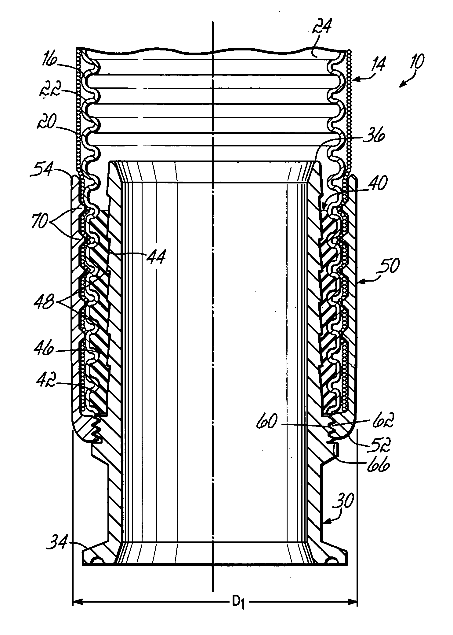
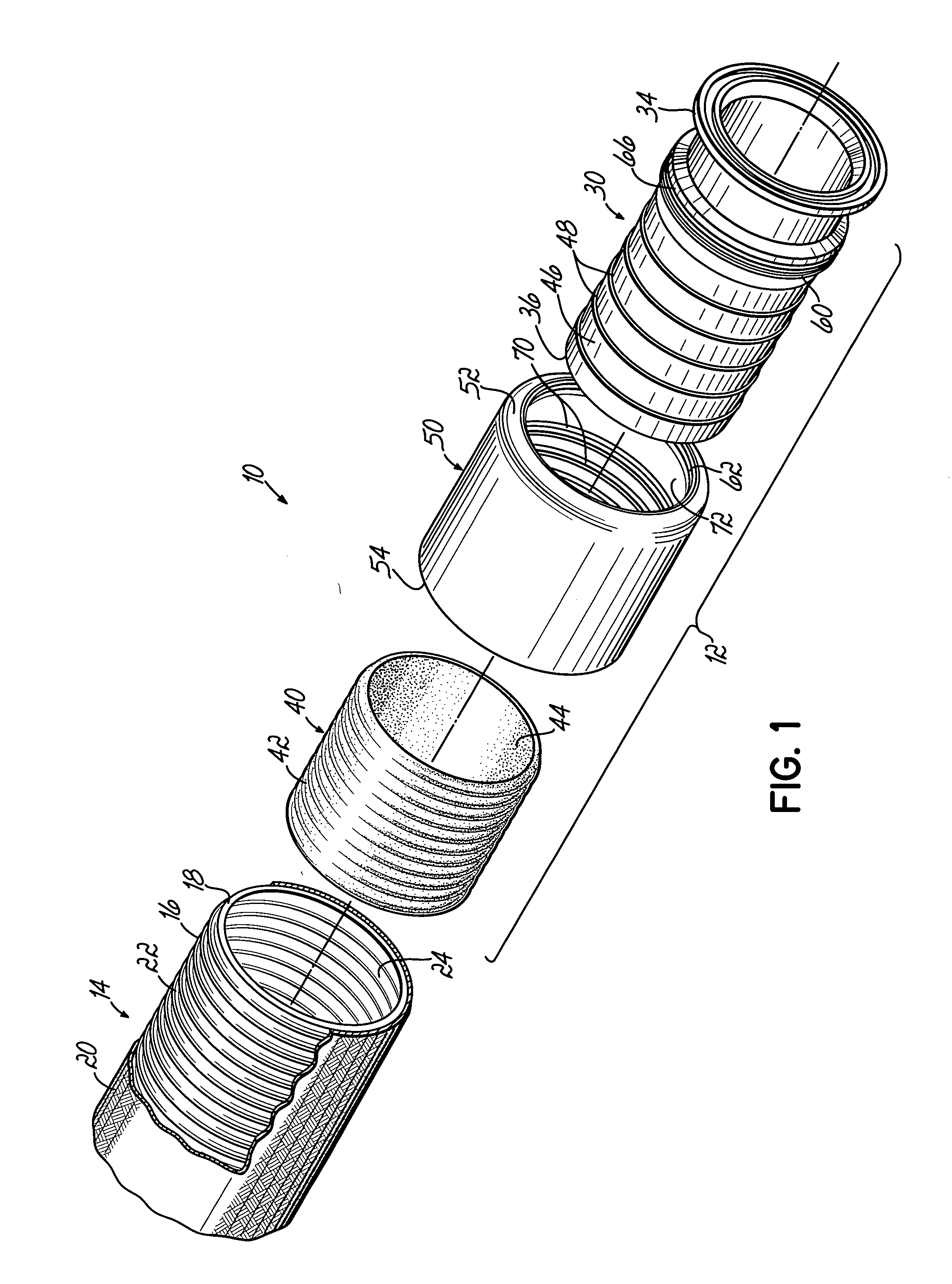
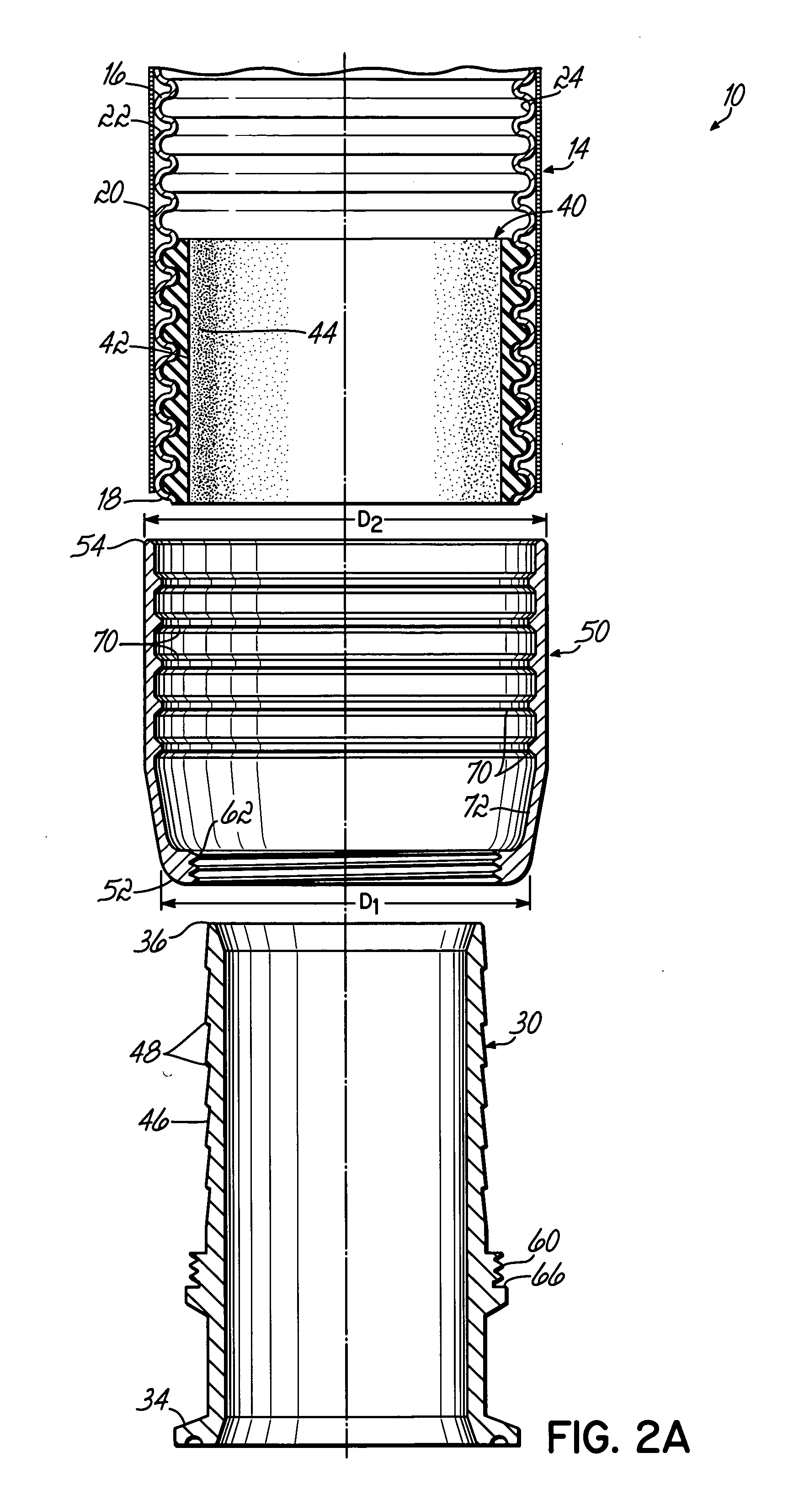
[0012]FIG. 1 depicts an exemplary flexible hose assembly 10 including an exemplary fitting 12 according to the present invention. The flexible hose assembly 10 includes a flexible hose 14 formed from corrugated metal tube 16 having a first end 18 configured to receive the fitting 12. In the embodiment shown, the metal tube 16 has annular corrugations, however it will be recognized that the corrugations may alternatively be formed in a spiral fashion, as known in the art. The hose 14 further includes a covering 20 that surrounds an outer surface 22 of the tube 16 and extends the length of the hose 14. In the embodiment shown, the covering 22 is a braided metal sheath, as known in the art. Due to the corrugations formed in the metal tube 16, the outer and inner surfaces 22, 24 of the tube 16 have undulating, contoured surfaces.

[0013] The fitting 12 is configured to be crimped to the first end 18 of the hose 14 and includes an elongated tubular stem 30, a sealing member 40, and a ferr...


PUM

PropertyMeasurementUnit
thicknessaaaaaaaaaa
thicknessaaaaaaaaaa
outer diameteraaaaaaaaaa

Abstract

A flexible hose formed from corrugated metal tube has a fitting permanently crimped to the end of the hose. The fitting includes an elongated stem having a first end adapted to be coupled to an appropriate fitting surface and a second end configured to be received within the hose. A sealing member disposed on the second end of the stem seals the fitting between the corrugated metal tube and the stem. A ferrule is placed over the hose and is crimped to compress the hose and sealing member between the ferrule and stem.

Description

FIELD OF THE INVENTION [0001] The present invention pertains generally to fittings for hose, pipe and other conduits, and more particularly to a fitting for a flexible hose or pipe formed from corrugated metal tube. BACKGROUND OF THE INVENTION [0002] Flexible hoses formed from corrugated metal tube are used in many applications where the hose is exposed to severe conditions or where the nature of the material conveyed through the hose requires the use of metal tubing. Advantageously, the corrugations lend some degree of flexibility to the metal tube. Typical uses of these hoses include applications where the hose is exposed to extreme hot and cold temperature conditions, where high pressure gas or liquid is transported through the hose, or when fluid permeability is a concern, such as in gas piping systems, refrigeration systems or the transport of chemical materials. These hoses also provide flexibility to fixed piping systems, for example, where adjacent fixed pipes must be joined...

Claims


Application Information

Patent Timeline
Patent Type & Authority Applications(United States)
IPC IPC(8): F16L25/00F16L33/207
CPCF16L33/2073Y10T29/49428Y10T29/49913Y10S285/903
Inventor FULLBECK, WOLFGANG F.HESS, MARK A.
Owner CHARLES C ASHDOWN ESQ AND J THOMAS MELLOTT ESQ CO TRUSTEES UNDER THE FULLBECK PATENT TRUST
Why Eureka
Try Eureka