Process for fabricating of a speaker enclosure having any preselected external, shape containing internal cavities shaped with preselected enhancements for each preselected driver mounted within said external shaped enclosure

a technology of pre-selected enhancements and enclosures, which is applied in the direction of packaging, labelling, transportation and packaging, etc., can solve the problems of distortion of the sound reproduction capability of the device, assembly of the device, and no prior art improvement teaching suggests substantially changing the outside shape of the box

Inactive Publication Date: 2005-02-03
MCCAIN KYLE
View PDF3 Cites 5 Cited by
  • Summary
  • Abstract
  • Description
  • Claims
  • Application Information

AI Technical Summary

Benefits of technology

[0029] In the preferred method, the method uses a number of templates forming each layer to define the external circumferential shape and any internal cutouts to define the internal circumferential shape of cavities, channels as well as supports and alignment guide holes. The templates are used to pattern a specific layer or slice of the desired final device. The layers are assembled by alignment of the alignment guide holes and thereafter a metal shaft having threaded ends and a nut on each end is inserted within the alignment guide holes to apply pressure to the layers by means of tightening the nuts thereby holding the layers together. This method allows the present invention to adept the outside shape and internal chambers and channels to reproduce music.

Problems solved by technology

However, none of teaching of the prior art improvements suggest substantially changing the outside shape of the box, which may also accommodate a modified inside shape as required for a driver selection.
However, assembly of the device as taught by the article with glue is a problem because as the glue holding the layers and separate units together ages, the environment of vibration of the speakers within the separate shapes used as parts to fabricate the enclosure for the selected drivers will result in separation of the parts and the layers used to form the parts.
Any separation will induce undesired vibration that will generate distortion of the sound reproduction capability of this device.
Nor does the article provide for securely attaching the individual shapes together.
Any separation will create unwanted vibrations and distortion of the sound reproduction ability of the speaker assembly.
However, the prior art teaching of speaker enclosures provides only limited teaching for reinforcement of the conventional boxlike construction of the enclosure to reduce vibration.

Method used


Image

  • Process for fabricating of a speaker enclosure having any preselected external, shape containing internal cavities shaped with preselected enhancements for each preselected driver mounted within said external shaped enclosure
  • Process for fabricating of a speaker enclosure having any preselected external, shape containing internal cavities shaped with preselected enhancements for each preselected driver mounted within said external shaped enclosure
  • Process for fabricating of a speaker enclosure having any preselected external, shape containing internal cavities shaped with preselected enhancements for each preselected driver mounted within said external shaped enclosure

Examples


Embodiment Construction

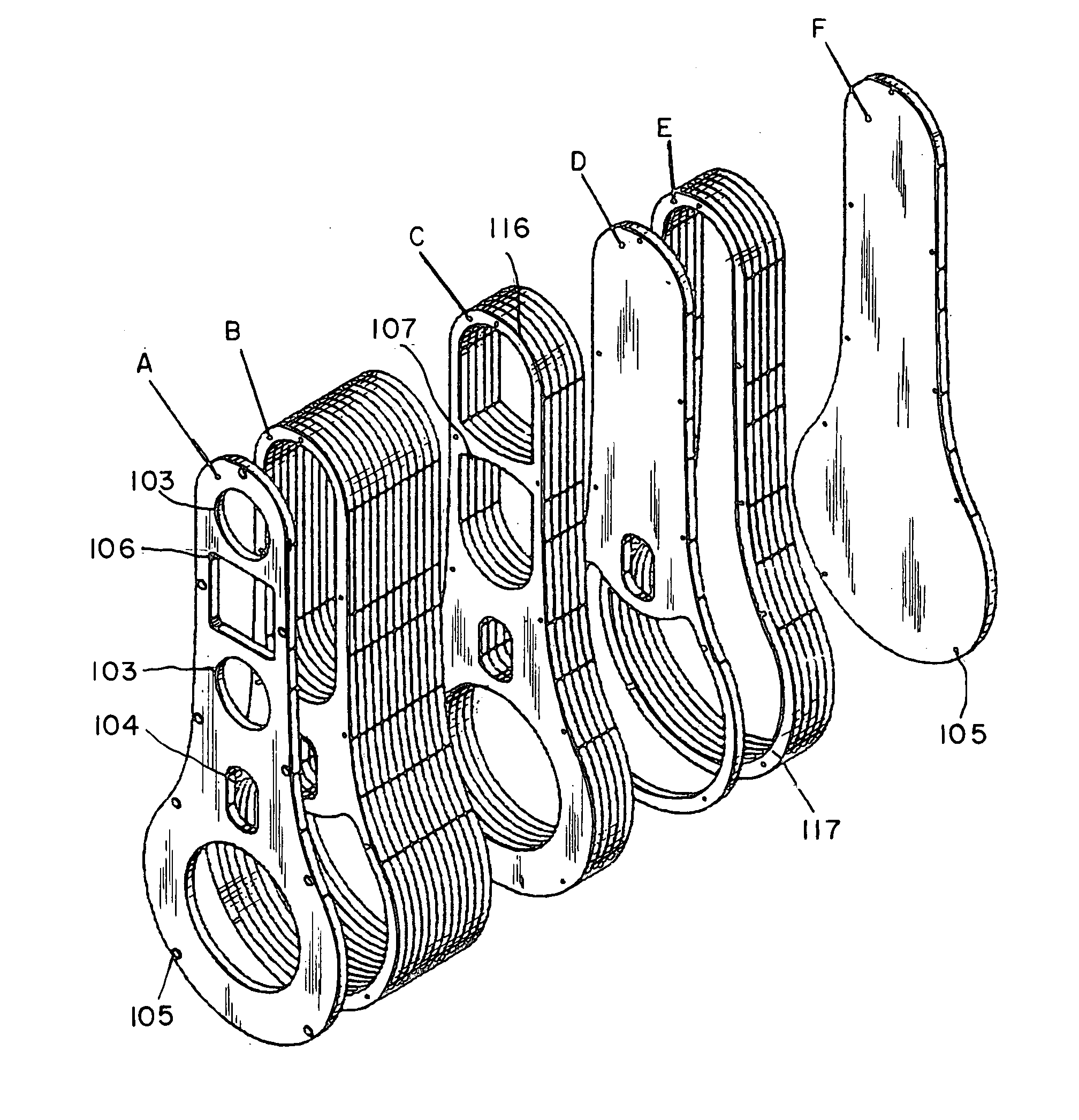
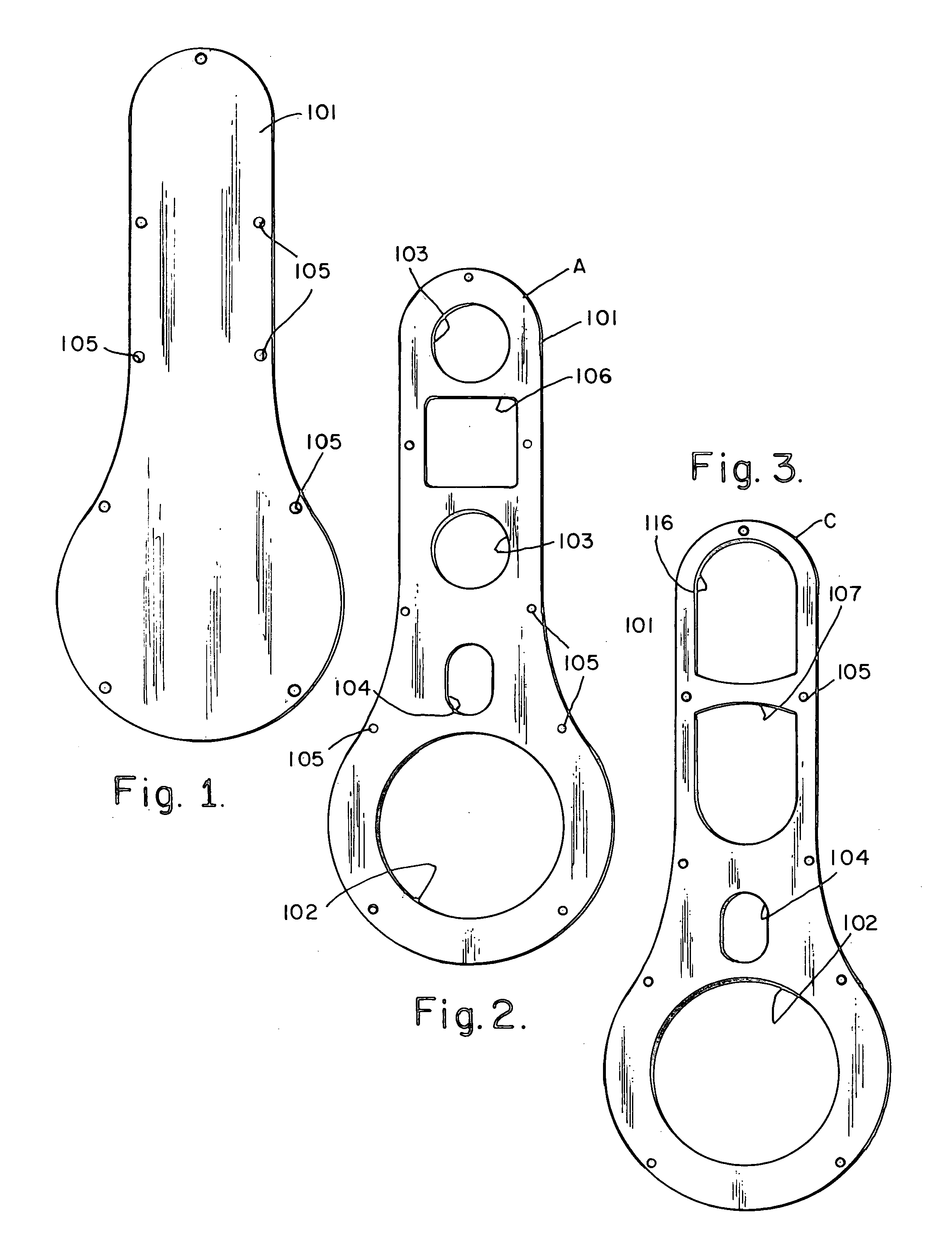
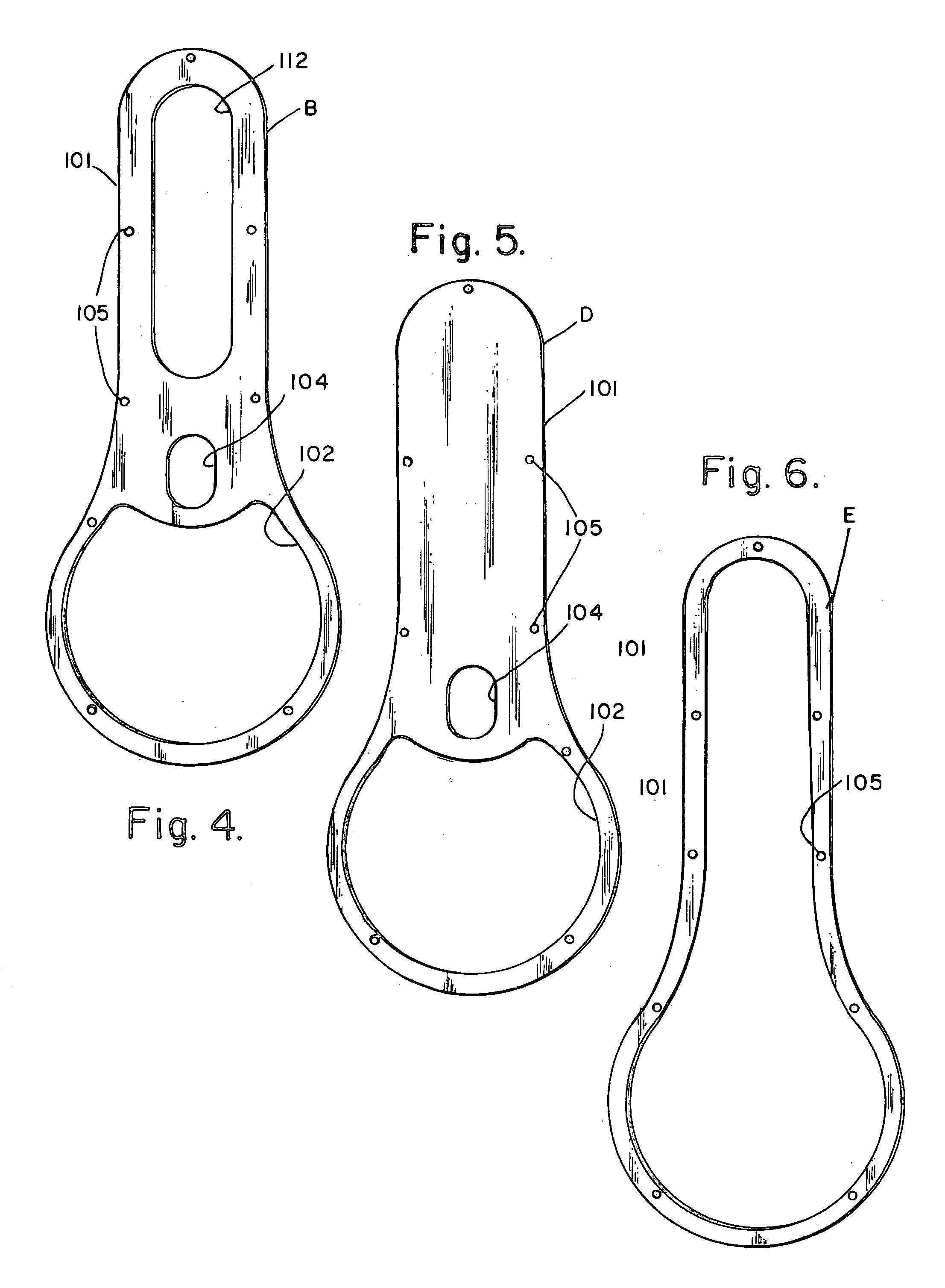
[0042] Referring now to the drawing, FIG. 1 shows the general circumferential shape 101 preselected to be the external shape of the enclosure fabricated according to the teaching of this invention. A preselected number of guide holes 105 are marked on this general template.

[0043]FIG. 2 shows the general template with internal circumferential shapes for a woofer cutout edge 102, mid-range cutouts edges 103, a port cutout edge 104 and a tweeter cutout edge 106 for the preselected set of drivers to be mounted within the assembled enclosure. The guide holes 105 set out on the general template of FIG. 1 are applied to the template of FIG. 2 to assist in alignment of the templates into the final assembled enclosure.

[0044]FIG. 3 shows the general template with guide holes 105 and an internal support 107 placed between chambers formed by internal circumferential edges 116 so as to not interfere with the mounting of the mid-range and tweeter drivers within the chamber formed by internal ci...


PUM

PropertyMeasurementUnit
angleaaaaaaaaaa
angleaaaaaaaaaa
angleaaaaaaaaaa

Abstract

A process for the fabrication of a speaker enclosure for a set of drivers utilizing a series of templates including a base template having an external circumferential edge, corresponding to the preselected external shape of the enclosure, a preselected number of guide holes placed within said circumferential edge, a plurality of internal circumferential edges creating mounts for each driver and corresponding port. The process includes the step of calculating the volumes of cavities to enhance the sound reproduction ability of the drivers. Additional templates including the external circumferential edge and guide hole placement of the base template and further including internal circumferential edges to complete the fabrication of the cavity volume further incorporating internal supports within said cavity volumes placed whereby said supports do not inhibit the mounting of said drivers into said cavities. Assembling the layers of sheet material cut along the external and internal edges of each template into a prototype of the enclosure and testing said prototype to measure the sound reproduction capability. Adjusting selected portions of internal circumferential edges to enhance the sound reproduction ability of the drivers mounted into the enclosure to create a master set of templates. Using the master set of templates to fabricate the layers, assembling the layers in the preselected order with guide holes aligned, applying glue to at least one side of each layer, inserting reinforcing rods having threaded ends into each guide hole and installing and tightening a nut onto each threaded end of said reinforcing rods to hold the layers in the preselected external shape without deforming the layers or distorting the sound reproduction ability of the enclosure.

Description

BACKGROUND OF THE INVENTION [0001] 1. Field of the Invention [0002] This invention relates to the art of designing and fabricating an enclosure for a speaker driver or set of drivers and more particularly providing the ability to produce any preselected external shape of the enclosure independently of the selected driver(s) while including the fabricating of internal cavities with selected shapes and / or positioned ports and connecting channels thereby allowing said internal cavities of said enclosure to provide enhancement ability for the reproduction of sound of the selected driver(s). This application is based upon the Provisional Patent filed Jul. 31, 2002 as Ser. No. 60 / 400,459. [0003] 2. Description of the Prior Art [0004] The art of designing and fabricating an enclosure for a speaker driver or set of drivers has a long history and many variations. As speaker enclosures have evolved from a simple box for one driver or for a set of drivers, the box has evolved to accommodate ea...

Claims


Application Information

Patent Timeline
Patent Type & Authority Applications(United States)
IPC IPC(8): H04R1/28
CPCH04R1/2888Y10T156/1093Y10T156/1062Y10T156/1092
Inventor MCCAIN, KYLE
Owner MCCAIN KYLE
Why Eureka
Try Eureka