Rotary broom attachment for traction vehicles

Inactive Publication Date: 2005-05-19
GREGERSON DENNIS JAMES
View PDF0 Cites 26 Cited by
  • Summary
  • Abstract
  • Description
  • Claims
  • Application Information

AI Technical Summary

Problems solved by technology

The inability to clearly see objects or people near the machine can have dire consequences.
Prior art methods of alleviating this pro

Method used


Image

  • Rotary broom attachment for traction vehicles
  • Rotary broom attachment for traction vehicles
  • Rotary broom attachment for traction vehicles

Examples


Embodiment Construction

FIGS. 3a, 3b, 3c, 3d, and 3e—Preferred Embodiment

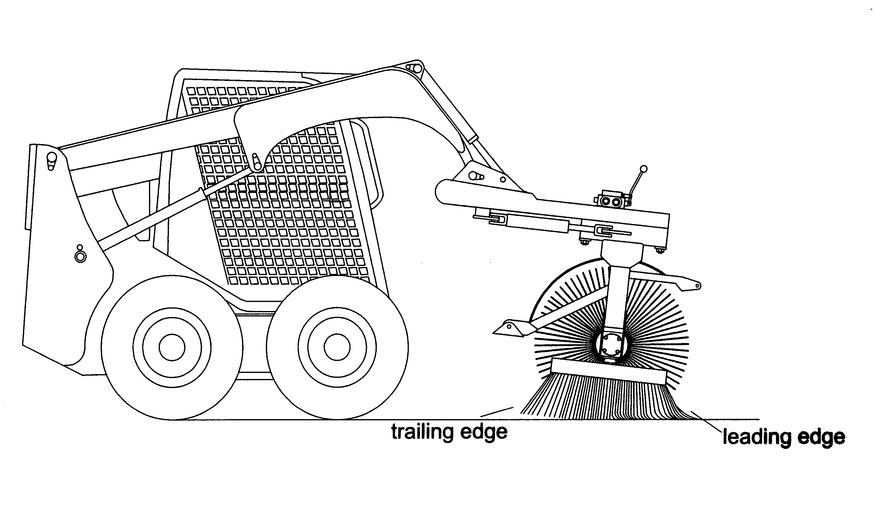
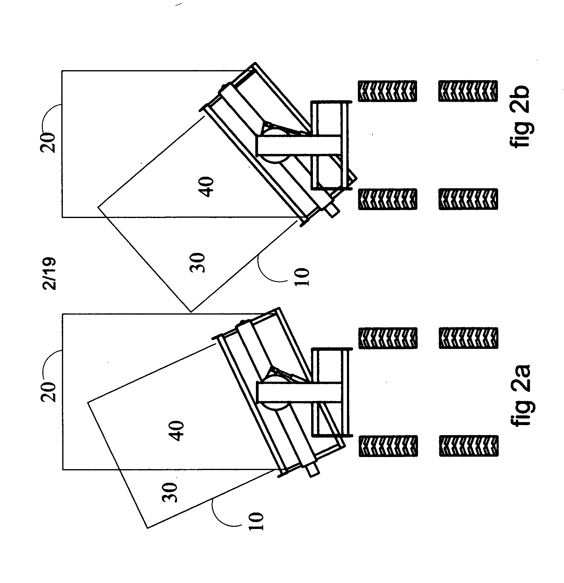
[0153]FIG. 3a shows the invention of a broom assembly 2 attached to a skid steer loader 1 in the parked position. FIG. 3b shows the invention in the work position of its preferred embodiment. A skid steer loader 1 is adapted for use in many industrial, agricultural and landscaping applications wherein easy maneuverability, power lifting and transporting capabilities are required. The skid steer loader 1 is provided with a pair of laterally spaced boom arms 1a that are driven along an arcuate path by hydraulic cylinders 1b. One end of the boom arms 1a are pivotally attached to the main body of the skid steer loader 1 on each side of the operator cab 1c. The opposite ends of the boom 1a arms are pivotally attached to the bottom of the “quick attach adapter”10d forming pivot joint 4 rotating about a pitch axis 5. The tube ends of hydraulic cylinders 1e are pivotally attached on the boom arms and the rod ends of hydraulic cylinders 1e are...


PUM


Abstract

A rotary brush assembly that is mounted to a traction vehicle such as a skid steer type vehicle in such a way to as to be capable of sweeping horizontal, vertical, and overhead surfaces. The device is capable of sweeping in close proximity to objects protruding from these surfaces. The assembly is attached to the vehicle such that the operator has and an unrestricted view of the swept surface immediate to the brush, allowing the operator to address skips as they occur.

Description

CROSS-REFERENCE TO RELATED APPLICATIONS FEDERALLY SPONSORED RESEARCH [0001] Not applicable. BACKGROUND OF THE INVENTION FIELD OF INVENTION [0002] This invention relates to rotary angle broom sweeping attachments for skid steer loaders. BACKGROUND OF THE INVENTION [0003] The concept of employing rotary brooms to sweep flat surfaces has been around for some time. Configurations for rotary brushes are either transverse, where the brush axis of rotation is parallel to the ground, or vertical, where the brush axis of rotation is perpendicular to the ground. There are also single brush configurations and multiple brush configurations. The present invention deals with both a transverse single brush that will be referred to as simply “the brush” and a single vertical brush that will be referred to as a “gutter broom”. It would be clear to one skilled in the art that this invention could be applied to other brush orientations and multiple brush assemblies as well. [0004] Numerous improvement...

Claims


Application Information

Patent Timeline
IPC IPC(8): E01H1/05E02F3/34E02F3/96
CPCE01H1/053E02F3/96E02F3/3414E01H1/056
Inventor GREGERSON, DENNIS JAMES
Owner GREGERSON DENNIS JAMES
Why Eureka
Try Eureka