Broom, method, and broom display

a technology of brooms and brooms, applied in the field of brooms, methods can solve the problems of brooms slipping between hanging rods, brooms being attached to brooms, and broom displays becoming unsightly, and achieve excellent utility and amenability to being displayed, and made very inexpensively.

Inactive Publication Date: 2005-01-27
FREUDENBERG HOUSEHOLD PROD LP
View PDF15 Cites 20 Cited by
  • Summary
  • Abstract
  • Description
  • Claims
  • Application Information

AI Technical Summary

Benefits of technology

[0009] In accordance with another embodiment of the invention, a broom comprises a body having a shaft side and a cleaning side, a shaft connected to the body at the shaft side, and a plurality of bristles that extend from the cleaning side. The bristles comprise a plurality of bunched bristles, which may be connected to a support disposed on or near the cleaning side, via fusion-bonding. In accordance with this embodiment of the invention, the broom has a non-planar splaying surface which supports the bristles and which extends the broom angle, i.e., the angle formed by the broom bristles. This configuration allows the bristles to extend through a broom angle of at least 35 degrees.
[0010] In practice a broom may incorporate a combination of the described embodiments. The broom can be made very inexpensively, and the broom will have excellent utility and amenability to being displayed on a pair of hanging rods.

Problems solved by technology

One problem in the broom art relates to the commercial display of brooms.
For many known brooms, it is easy for the brooms to become dislodged, thus causing the broom display to become unsightly.
In addition, it is easy for many brooms to twist about the axis defined by the shaft, thus causing the broom to slip between the hanging rods.
Another problem relates to attaching the bristles to the broom.
Stapling of bristles can be somewhat unsatisfactory because the bristles are prone to falling out.
This technique has been found to provide a more satisfactory synthetic fiber broom than a stapled broom, because it is more difficult to disengage the fusion-bonded bristles from the substrate than it is to remove stapled bristles.
It has proven difficult to fusion-bond bristles to a substrate at an angle of more than 15 degrees off perpendicular to a tangent to the substrate.

Method used


Image

  • Broom, method, and broom display
  • Broom, method, and broom display
  • Broom, method, and broom display

Examples


Embodiment Construction

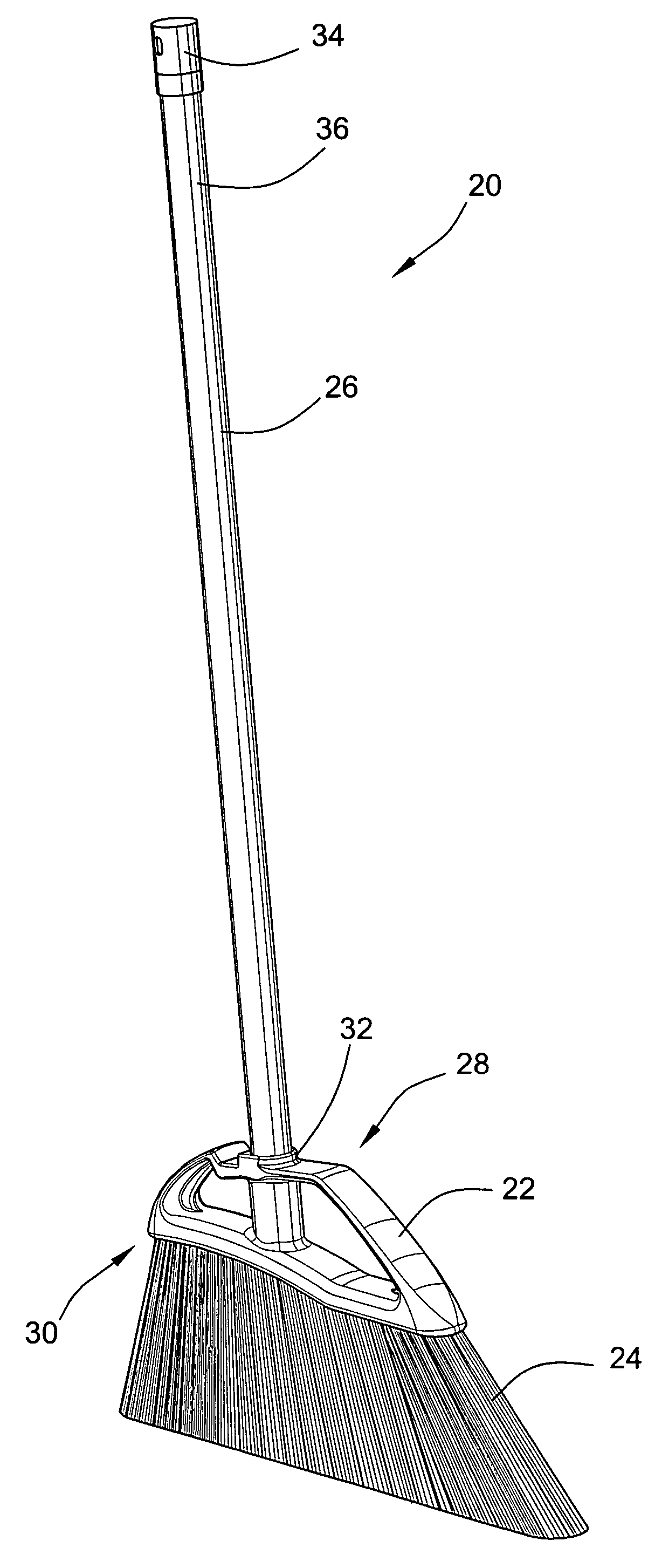
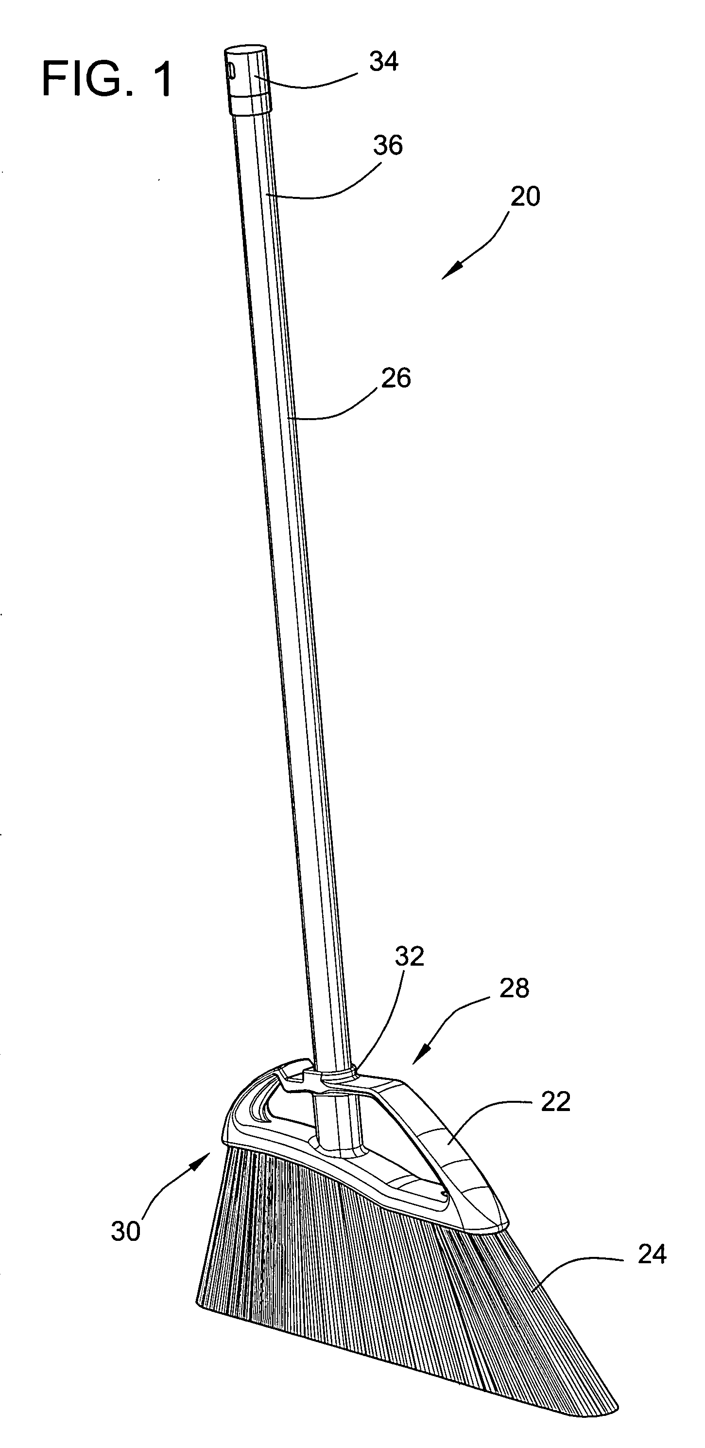
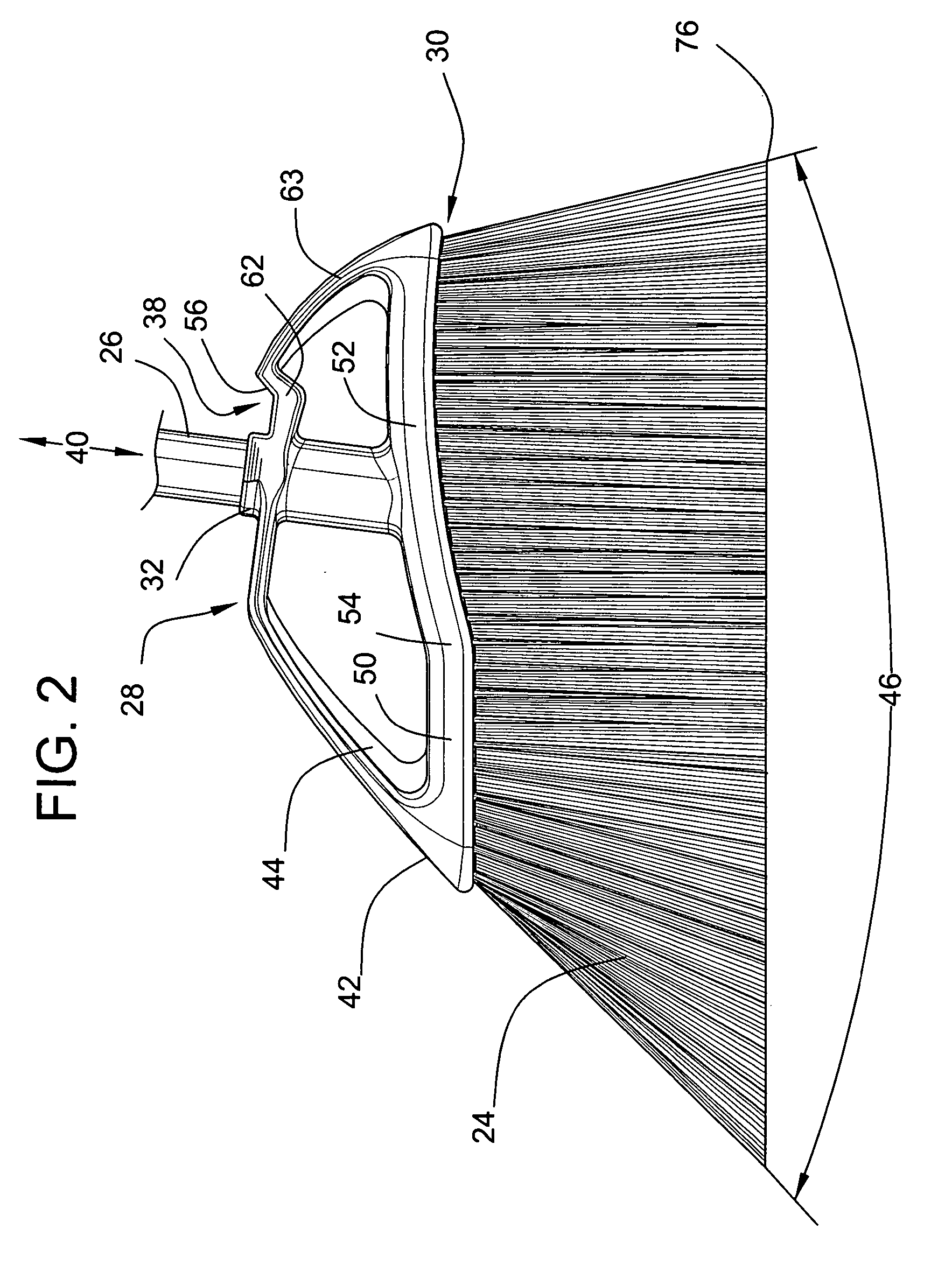
[0036] With reference to FIG. 1, the illustrated broom 20 includes a broom body 22, bristles 24, which are disposed in a plurality of bunches, and a shaft 26. The broom body 22 having a shaft side 28 and a cleaning side 30. The bristles 24 extending from the cleaning side 30 of the broom body 22. Typically, the bristles 24 include a plurality of fibers and are attached to the broom body 22. In one embodiment, the bristles 24 are stapled to the body 22. The broom body 22 includes an integrally attached shaft connector 32. The shaft 26 is adapted to be connected to the broom body 22 at the shaft connector 32 on the shaft side 28. A hanging cap 34 is disposed at the operator end 36 of the shaft 26. The components of the broom may be made of any suitable materials and by any suitable techniques. For instance, the shaft may be made of steel, the broom body and hanger cap may be made of a suitable thermoplastic, and the bristles may be made of a suitable thermoplastic material. The bristl...


PUM

PropertyMeasurementUnit
broom angleaaaaaaaaaa
angleaaaaaaaaaa

Abstract

The broom may include a body, a shaft connected to the body, and a plurality of bristles extending from the body. The body may include a hanging shoulder disposed proximal to the shaft connector and a transverse retaining ridge disposed proximal the hanging shoulder. The retaining ridge limits rotation of the broom when hanging from a support. In another embodiment, the broom may include a body, a shaft, a support and a plurality of bristles extending from the support. The bristles are a plurality of bunched fibers which are connected to the support via fusion-bonding.

Description

CROSS-REFERENCE TO RELATED PATENT APPLICATION [0001] This patent application claims the benefit of priority to U.S. Provisional Patent Application No. 60 / 484,868, filed Jul. 3, 2003, and entitled “Broom, Method, and Broom Display,” which is incorporated in its entirety herein by this reference.FIELD OF THE INVENTION [0002] The invention is in the field of cleaning implements, and in particular is directed toward brooms, methods for the manufacture of brooms and toward a hanging broom display. BACKGROUND OF THE INVENTION [0003] One problem in the broom art relates to the commercial display of brooms. In consumer display racks, the brooms are generally hung from a pair of hanging rods, with the bristles extending upwardly and with the shaft extending downwardly between the hanging rods. For many known brooms, it is easy for the brooms to become dislodged, thus causing the broom display to become unsightly. In addition, it is easy for many brooms to twist about the axis defined by the ...

Claims


Application Information

Patent Timeline
Patent Type & Authority Applications(United States)
IPC IPC(8): A46B1/00A46B3/06A46B7/04A46B9/02A46B9/04
CPCA46B3/06A46B7/04A46B2200/302A46B9/026A46B9/02A46B5/00
Inventor BOYER, CHRISTOPHER T.MOLEK, TIMOTHY J.SPECHT, PAUL B.
Owner FREUDENBERG HOUSEHOLD PROD LP
Why Eureka
Try Eureka