Spatial accuracy assessment of digital mapping imagery

a technology of spatial accuracy and mapping imagery, applied in the field ofphotogrammetric mapping, can solve the problems of difficult definition of clear and unique geometric standards for such systems (in analogy to their analog counterparts), limited validation process, and inability to guarantee the accuracy of each and every imaging mission, so as to achieve robust and accurate correspondence, the effect of increasing the number of images resulting from typical triangulation missions

Inactive Publication Date: 2012-03-15
ZALMANSON GARRY HAIM
View PDF1 Cites 21 Cited by
  • Summary
  • Abstract
  • Description
  • Claims
  • Application Information

AI Technical Summary

Benefits of technology

[0016]We now generalize the previous discussion on accuracy assessment to comparing more than just one ray. That is realized by comparing the external orientation (geo-referencing) of the image of interest with that of another geo-referenced image the external orientation accuracy of which is assumed to be known and error-free. More specifically, that means comparing (in the way to be described in the following) a set of N corresponding pairs of line-of-sight rays associated with conjugate pixels in the target and reference images respectively, a procedure yielding the discrepancy results encoded in the Spatial Accuracy of Geo-referenced Image (SAGI) measure.
[0017]An additional merit of this invention is its provision to robustly support autonomous validation (certification) procedures based on image matching techniques. Due to its special set-up requirement, utilizing reference images that were taken in close spatial vicinity to the target image (see details in the sequel) many of the typical problems associat...

Problems solved by technology

While theoretically it is possible to self-calibrate any optical system turning it into a proper mapping device, in reality, guaranteeing it for each and entire imaging mission is not that simple.
All these make the definition of a clear and unique geometric standard for such systems (in analogy to their analog counterparts) pretty challenging.
One obvious disadvantage even beyond the costs involved in setting up and maintaining the te...

Method used


Image

  • Spatial accuracy assessment of digital mapping imagery
  • Spatial accuracy assessment of digital mapping imagery
  • Spatial accuracy assessment of digital mapping imagery

Examples


Embodiment Construction

[0025]1. Terminology and Notations

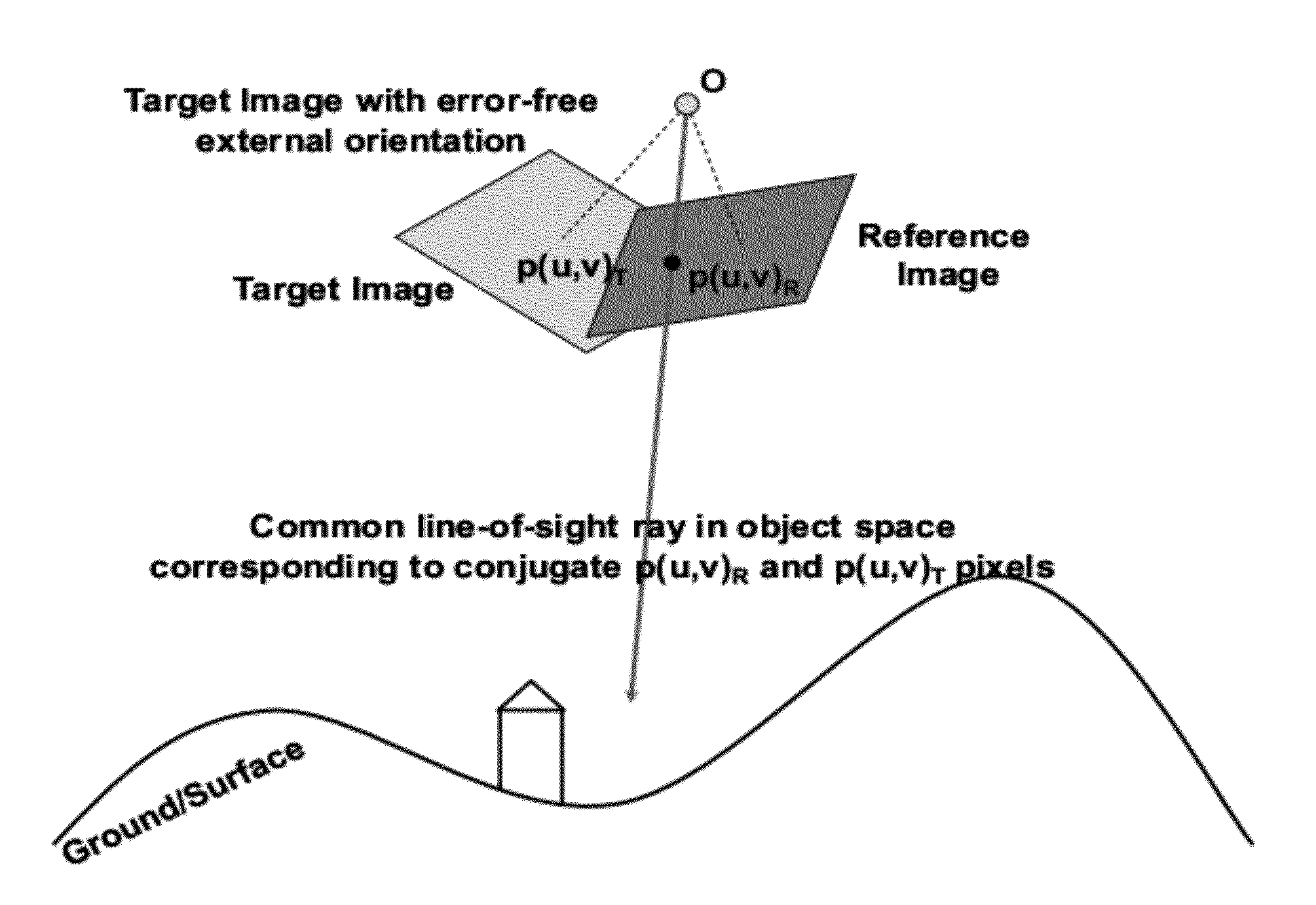
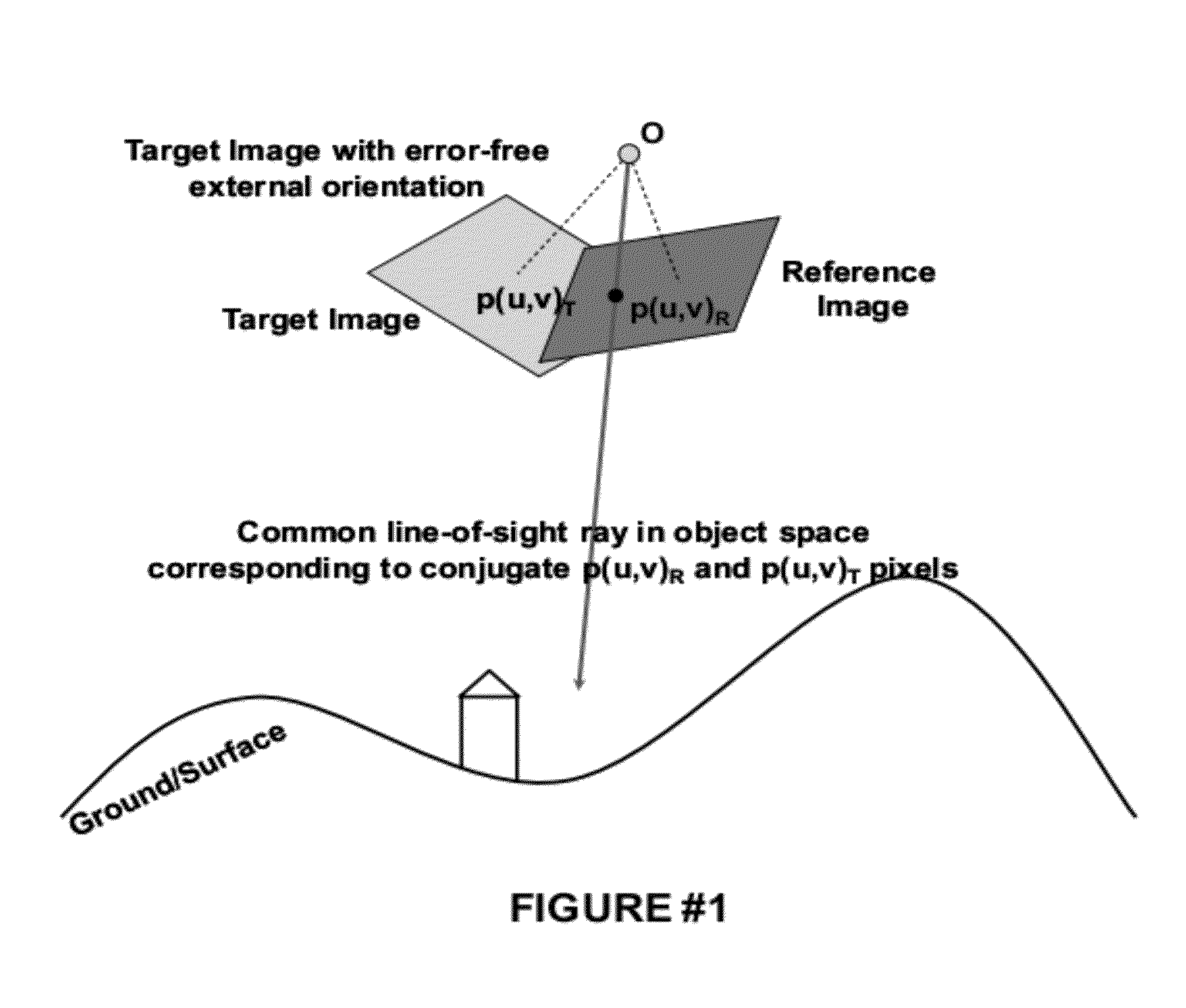
[0026]A geo-referenced optical image is a Line-Of-Sight measurement device. It associates a 3D straight line in object space with every given pixel p(u,v) in that image. From geometric point of view that means that this 3D line is the geometric place of all points in space which project into p(u,v). Analytically speaking, a geo-referenced image is assigned with the so-called external orientation information which in turn can be represented either explicitly or implicitly. In the explicit representation (also entitled as rigorous photogrammetric model) the line-of-sight originating from pixel p(u,v) can be easily computed from the external orientation parameters (decomposed into interior and exterior orientation) to result with the parametric 3D line in space represented parametrically by [X(τ) Y(τ) Z(τ)]T=[XC YC ZC]T+[ux uy uz]Tτ where [XC YC ZC]T is the 3D camera position in space at the time of the exposure and [ux uy uz]T is a unit direction alon...


PUM


Abstract

The present invention defines a quantitative measure for expressing the spatial (geometric) accuracy of a single optical geo-referenced image. Further, a quality control (QC) method for assessing that measure is developed. The assessment is done on individual images (not stereo models), namely, an image of interest is compared with automatically selected image from a geo-referenced image database of known spatial accuracy. The selection is based on the developed selection criterion entitled “generalized proximity criterion” (GPC). The assessment is done by computation of spatial dissimilarity between N pairs of line-of-sight rays emanating from conjugate pixels on the two images. This innovation is sought to be employed in any optical system (stills, video, push-broom, etc), but its primary application is aimed at validating photogrammetric triangulation blocks that are based on small (<10 MPixels) and medium (<50 MPixels) collection systems of narrow and dynamic field of view together with certifying the respective collection systems.

Description

BACKGROUND OF THE INVENTION[0001]1. Field of the Invention[0002]The primary usage of the present invention is in the field of photogrammetric mapping from optical aerial imagery with an emphasis on small and medium format and / or field of view (FOV) systems mostly based on general purpose cameras (stills, video). This invention is intended to serve as the central component of geometric accuracy validation1 analysis for imagery-based spatial IT products. We envision its wide acceptance as part of certification procedures for new digital imagery systems used for geographic information (GI) acquisition. Throughout this invention document we use the terms validation and assessment interchangeably1 [0003]2. Description of the Prior Art[0004]Introduction of digital aerial cameras during the 2000 ISPRS (International Society of Photogrammetry and Remote Sensing) congress in Amsterdam provided the final missing link for turning the photogrammetric mapping production workflows into fully digi...

Claims


Application Information

Patent Timeline
IPC IPC(8): G06K9/00
CPCG01C11/04
Inventor ZALMANSON, GARRY HAIM
Owner ZALMANSON GARRY HAIM
Why Eureka
Try Eureka