
Method of hidden surface reconstruction for creating accurate three-dimensional images converted from two-dimensional images

a three-dimensional image and hidden surface technology, applied in the field of hidden surface reconstruction, can solve the problems of inability to detect the edges of the difference between the left and right eye view, and the simple repetition of background pixels across the gap

Inactive Publication Date: 2005-05-19
REALD DDMG ACQUISITION LLC
View PDF65 Cites 81 Cited by
  • Summary
  • Abstract
  • Description
  • Claims
  • Application Information

AI Technical Summary

Benefits of technology

"The patent text describes a method for converting 2D motion picture images into 3D images. The method addresses the issue of creating a 3D perspective image by repositioning objects in the image. It also addresses the issue of creating a consistent and uniform depth perception by the brain when viewing the image. The method uses pixel repeating to fill the gap of missing pixels caused by the repositioning of objects. The technical effect of the patent is to reduce or eliminate image artifacts that occur during the conversion of 2D images into 3D images."

Problems solved by technology

In many cases, this approach is sufficient even though the pixel repeat information is not an exact replica of the pixel information that should actually be present in the gap of missing information.
As long as the pixel repeat gap is not extensively large (which would occur if the object happens to move a great distance toward or away from the viewer) and as long as the repeat pixel information does not exhibit any type of motion artifacts relative to its adjacent surrounding backgrounds, simply “pixel repeating” background pixels across the gap often goes unnoticeable.
The fact that the image seen by one eye contains pixel repeat information can, in many cases, go quite undetectable.
Even in a real photographed 3D image, the edges of foreground against background result in edges differences between the left and right eye views.
It is when the differences become too great and inconsistent with the flow of the image content that the brain stimulates human senses to consciously perceive such image artifacts as distracting and / or unreal.
This may either be because the gap is too wide or because there may be too much activity of motion near the edge of the object by other objects.
In this case, the area of pixel fill is simply not a good fit and results in a visual distraction.

Method used


Image

  • Method of hidden surface reconstruction for creating accurate three-dimensional images converted from two-dimensional images
  • Method of hidden surface reconstruction for creating accurate three-dimensional images converted from two-dimensional images
  • Method of hidden surface reconstruction for creating accurate three-dimensional images converted from two-dimensional images

Examples


Embodiment Construction

[0021] The following is a detailed description of the best presently known mode of carrying out the invention. This description is not to be taken in a limiting sense, but is made merely for the purpose of illustrating the general principles of the invention.

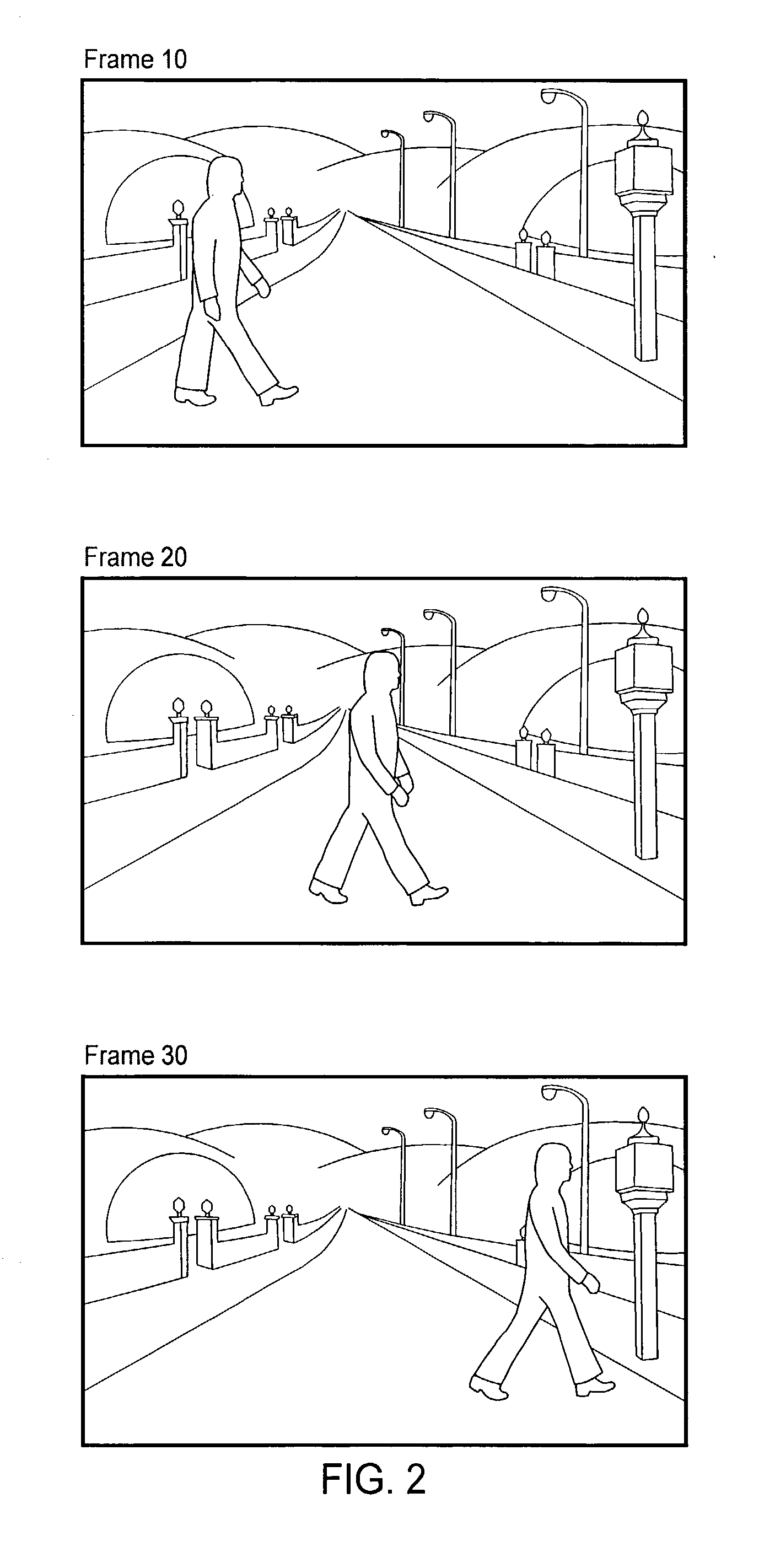
[0022] In order to recreate a high quality, realistic three-dimensional image from a two-dimensional image, conversion artifacts must be eliminated, or at least minimized. The methods of the present invention eliminate or significantly reduce pixel fill artifacts. Various methods of the present invention generally involve retrieving missing pixel information for object separation gaps from other frames or images.

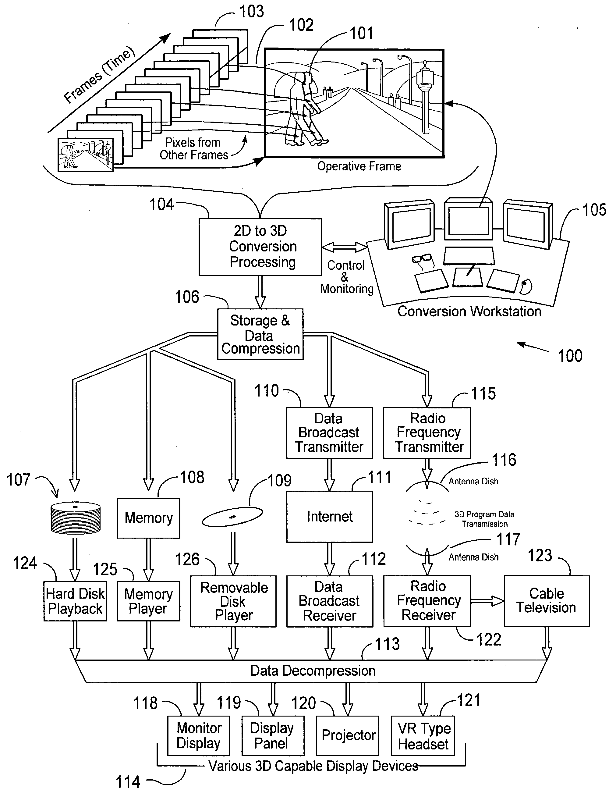
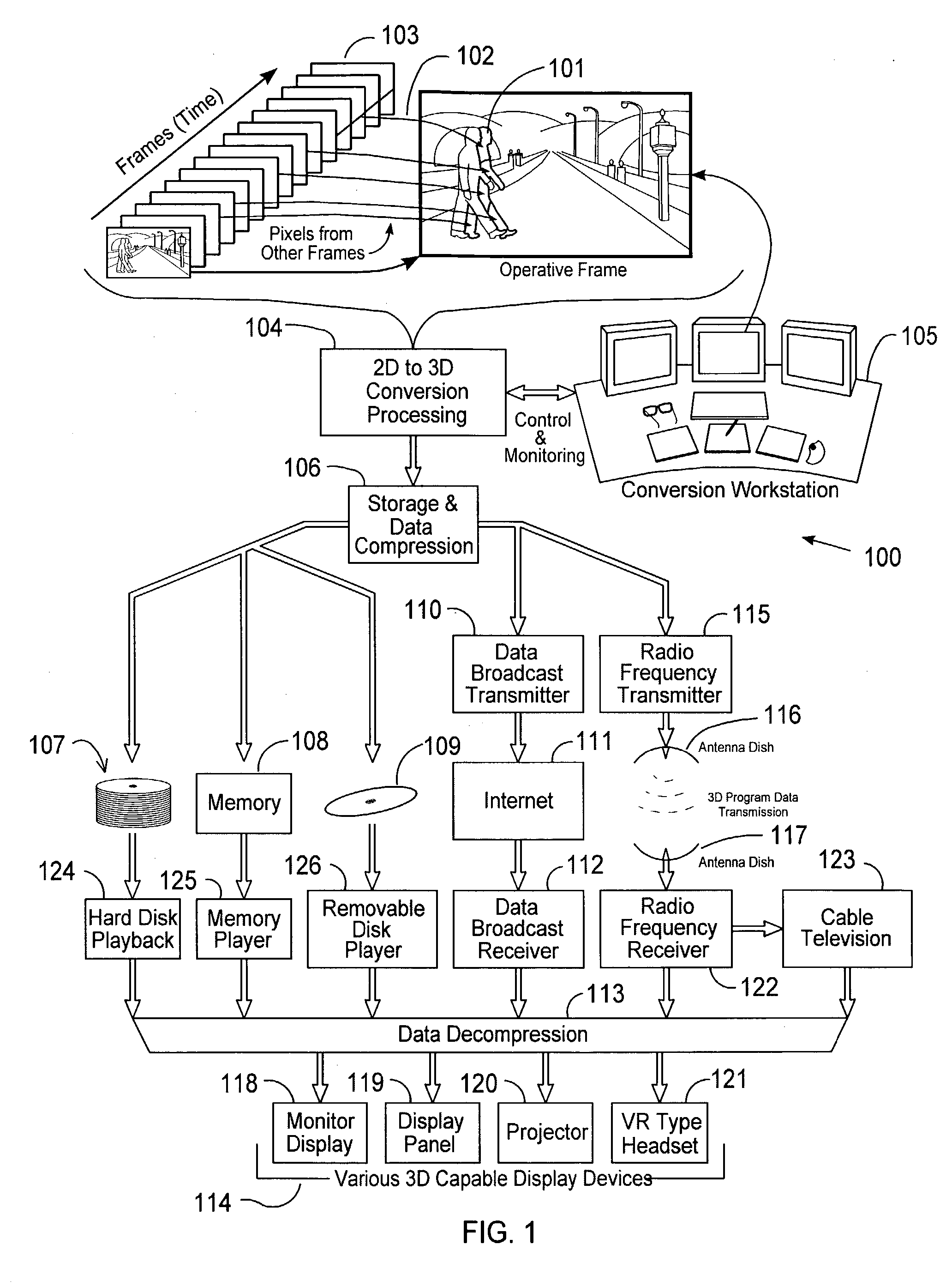
[0023]FIG. 1 shows an exemplary system 100 suitable for implementing the various methods of the present invention. During the process of converting images into 3D images, the original positions of image objects are shifted to adjust the perceived depths of the objects in the resulting 3D images forward or back toward t...


PUM


Abstract

An exemplary method of reconstructing a hidden surface area in an image includes the steps of: identifying a separation pixel gap in an image resulting from a repositioning of image pixels to create a three-dimensional image; identifying pixels from one or more images; and filling the separation pixel gap with the pixels. Replacement pixels can be retrieved from a single image in a search sequence of images, or from a plurality of images in the sequence. One or more pixel fill techniques can be employed to determine replacement pixels for the separation pixel gap which best match adjacent background pixels.

Description

CROSS-REFERENCE TO RELATED APPLICATIONS [0001] This application is a continuation-in-part of U.S. patent application Ser. No. 10 / 147,380 entitled “Method For Conforming Objects To A Common Depth Perspective For Converting Two-Dimensional Images Into Three-Dimensional Images” filed on May 15, 2002, which is a continuation-in-part of U.S. patent application Ser. No. 10 / 029,625 entitled “Method And System For Creating Realistic Smooth Three-Dimensional Depth Contours From Two-Dimensional Images” filed on Dec. 19, 2001, which is a continuation-in-part of U.S. patent application Ser. No. 09 / 819,420 entitled “Image Processing System and Method for Converting Two-Dimensional Images Into Three-Dimensional Images” filed on Mar. 26, 2001, which is a continuation-in-part of U.S. patent application Ser. No. 09 / 085,746 entitled “System and Method for Converting Two-Dimensional Images into Three-Dimensional Images” filed on May 27, 1998, now U.S. Pat. No. 6,208,348, all of which are incorporated ...

Claims


Application Information

Patent Timeline
Patent Type & Authority Applications(United States)
IPC IPC(8): G06T3/00
CPCG06T5/005G06T2200/24G06T19/00G06T5/77
Inventor KAYE, MICHAEL C.BEST, CHARLES J. L.
Owner REALD DDMG ACQUISITION LLC
Learn More