
Spacer grid for nuclear reactor fuel assemblies

a spacer grid and fuel assembly technology, applied in nuclear engineering, greenhouse gas reduction, nuclear elements, etc., can solve the problems of difficult grid manufacturing, troublesome grid shape, and troublesome grid shape, so as to reduce prevent fretting corrosion of fuel rods, and improve the cooling efficiency of fuel rods of reactor fuel assemblies

Inactive Publication Date: 2005-05-19
KOREA ATOMIC ENERGY RES INST
View PDF22 Cites 28 Cited by
  • Summary
  • Abstract
  • Description
  • Claims
  • Application Information

AI Technical Summary

Benefits of technology

[0013] Accordingly, the present invention has been made keeping in mind the above problems occurring in the prior art, and an object of the present invention is to provide a spacer grid for nuclear reactor fuel assemblies, which has a grid spring at a central portion of each unit strip of perimeter strips thereof so that the grid springs of the perimeter strips are in equiangular surface contact with longitudinal fuel rods in a nuclear reactor fuel assembly, different from the conventional spacer grids, thus reducing fretting corrosion of the fuel rods, and which is provided, on an upper edge of some unit strips of the perimeter strips, with both a guide vane to enhance the intensity of cross flows of the coolant passing through the spacer grid and a guide tap free from disturbing the cross flows of the coolant, thus improving the thermal redundancy of the spacer grid, due to the enhanced cross flows of the coolant.
[0014] In conventional spacer grids for nuclear reactor fuel assemblies, the grid springs and dimples of the inner and perimeter strips are in non-equiangular surface contact or linear contact with fuel rods, so that the fuel rods may slide or move relative to the grid springs and dimples at the contact surfaces thereof, thus causing the fretting corrosion of the fuel rods in the reactor core. Therefore, to prevent the fretting corrosion of the fuel rods in the reactor core, the grid springs and dimples of the inner and perimeter strips must be designed to be in equiangular surface contact with the fuel rods. However, due to a geometrical limit, it is very difficult to manufacture the shape of the grid springs, which are provided on unit corner strips of the perimeter strips defining the outermost corner cells of a spacer grid, such that the grid springs establish the equiangular surface contact with neighboring fuel rods. Therefore, in the present invention, the entire grid springs of the perimeter strips of the spacer grid are designed such that a central part of each of the grid springs, at which the grid spring is in contact with a fuel rod, has a design capable of establishing the equiangular surface contact with the fuel rod, and the remaining part of the grid spring at which the grid spring supports an external load has a simple beam shape.
[0015] Furthermore, when the guide vanes, which are provided on the upper edges of the perimeter strips to guide the flows of the coolant in an effort to improve the fuel rod cooling efficiency of the reactor fuel assembly, are arranged in the same manner in the entire outermost cells of the spacer grid, the cross flows of the coolant in the reactor fuel assembly may be disturbed by the guide vanes provided in some outermost cells. In the above state, the object of improving the thermal redundancy of the spacer grid by generating the cross flows of the coolant between neighboring fuel assemblies is beyond a design purpose, due to the guide vanes disturbing the cross flows of the coolant. Therefore, in the present invention, some unit strips of the perimeter strips which define some outermost cells required to guide the cross flows of the coolant to neighboring fuel rods are designed to have guide vanes capable of guiding the cross flows of the coolant, and the remaining unit strips of the perimeter strips which define the remaining outermost cells free from the function of guiding the cross flows of the coolant are designed to have only the guide taps without the guide vanes. Therefore, the spacer grid of the present invention reduces interference between the fuel rods and the spacer grid during an insertion or removal of the fuel rods into or from the reactor core.

Problems solved by technology

In conventional spacer grids for nuclear reactor fuel assemblies, the grid springs and dimples of the inner and perimeter strips are in non-equiangular surface contact or linear contact with fuel rods, so that the fuel rods may slide or move relative to the grid springs and dimples at the contact surfaces thereof, thus causing the fretting corrosion of the fuel rods in the reactor core.
However, due to a geometrical limit, it is very difficult to manufacture the shape of the grid springs, which are provided on unit corner strips of the perimeter strips defining the outermost corner cells of a spacer grid, such that the grid springs establish the equiangular surface contact with neighboring fuel rods.
Furthermore, when the guide vanes, which are provided on the upper edges of the perimeter strips to guide the flows of the coolant in an effort to improve the fuel rod cooling efficiency of the reactor fuel assembly, are arranged in the same manner in the entire outermost cells of the spacer grid, the cross flows of the coolant in the reactor fuel assembly may be disturbed by the guide vanes provided in some outermost cells.
In the above state, the object of improving the thermal redundancy of the spacer grid by generating the cross flows of the coolant between neighboring fuel assemblies is beyond a design purpose, due to the guide vanes disturbing the cross flows of the coolant.

Method used


Image

  • Spacer grid for nuclear reactor fuel assemblies
  • Spacer grid for nuclear reactor fuel assemblies
  • Spacer grid for nuclear reactor fuel assemblies

Examples


Embodiment Construction

[0032] Reference will now be made in detail to the present preferred embodiments of the present invention, examples of which are illustrated in the accompanying drawings, wherein like reference numerals refer to like elements throughout. The embodiments are described below in order to explain the present invention by referring to the figures.

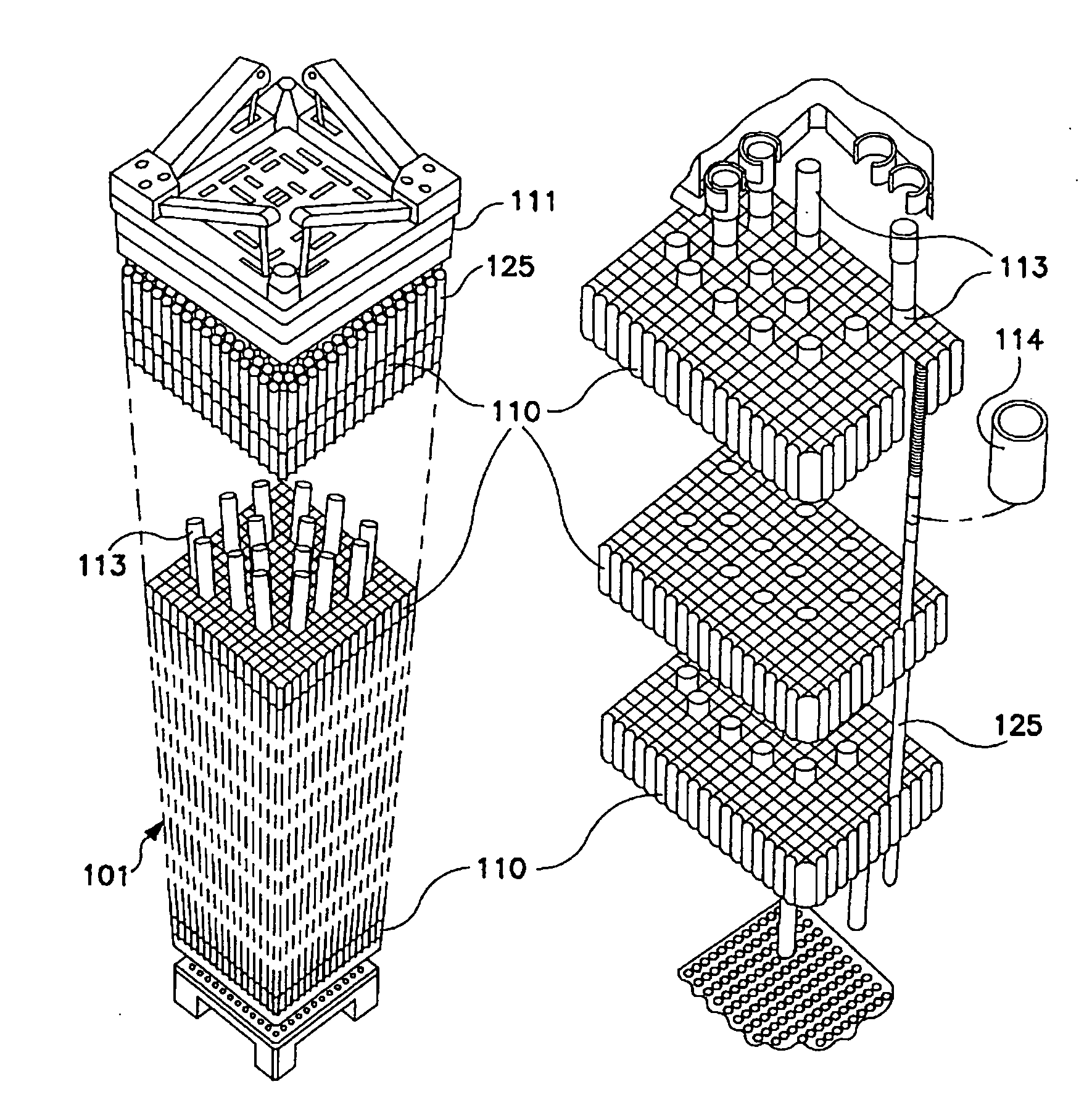
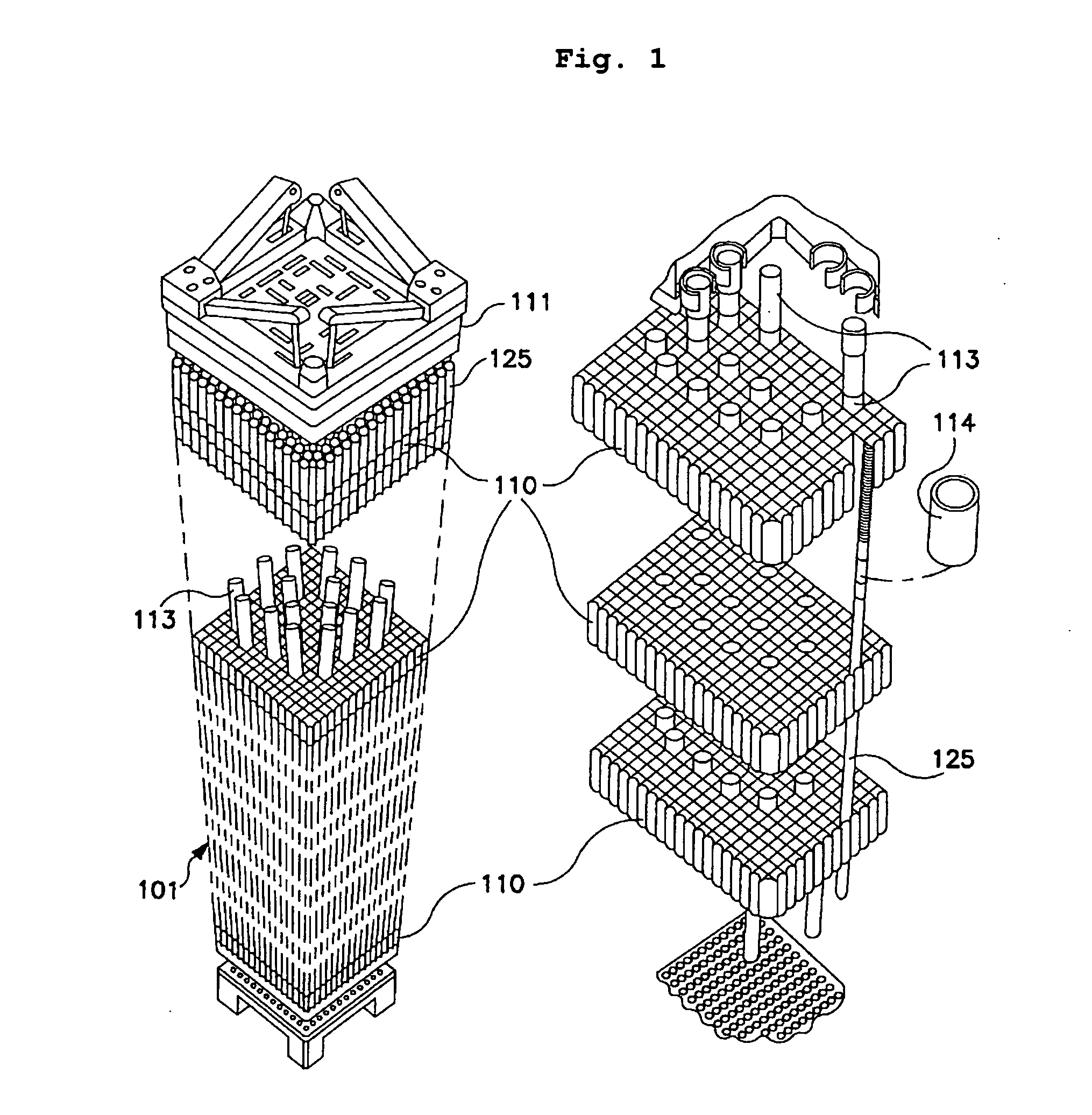
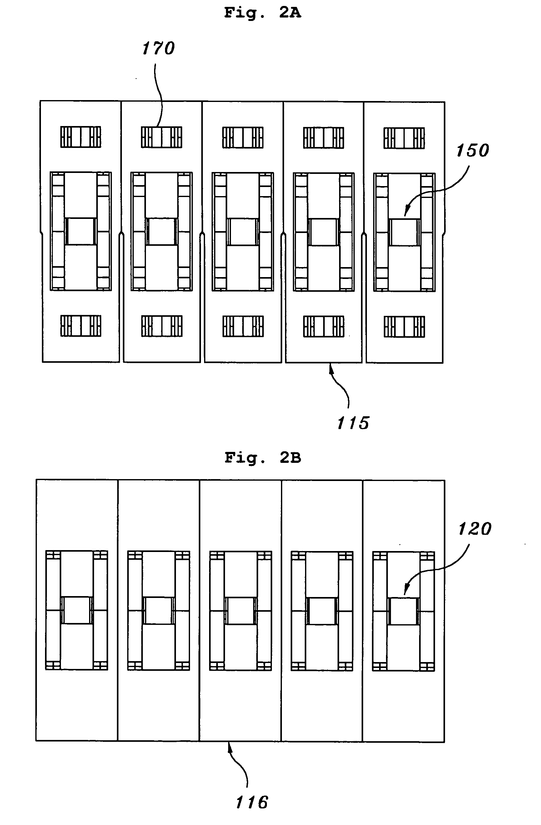
[0033] The spacer grid for nuclear reactor fuel assemblies according to the present invention is used in the reactor fuel assembly 101 of FIG. 1. Particularly, the spacer grid of the present invention is preferably used in a pressurized water reactor fuel assembly. As shown in FIGS. 4, 5A, 5B, 7A and 7B, the spacer grid of the present invention designated by the reference numeral 10 includes a plurality of perimeter strips each of which is fabricated with a plurality of unit intermediate strips 40 to encircle the intersecting inner strips and two unit corner strips 41 to form the outermost corner cells of the spacer grid 10. The perimeter strip...


PUM


Abstract

A spacer grid used for placing and supporting fuel rods in nuclear reactor fuel assemblies is disclosed. The spacer grid of this invention has a plurality of inner strips intersecting each other to form a plurality of guide tube cells and a plurality of fuel rod cells, with a plurality of mixing blades projecting upward from the inner strips at intersections of the inner strips. The spacer grid further includes a plurality of perimeter strips to encircle the intersecting inner strips. Each of the perimeter strips is fabricated with a plurality of unit intermediate strips and a plurality of unit corner strips, with a grid spring provided on each of the unit strips. The grid spring includes a vertical opening formed at a central area of each of the unit strips, a vertical support part extending vertically between the central portions of top and bottom edges of the vertical opening, and a fuel rod support part provided at a central portion of the vertical support part while being bent to have an outward rounded cross-section. The vertical support part is bent at two steps, and the fuel rod support part is bent to be in equiangular contact with each of the fuel rods, thus accomplishing a uniform contact pressure distribution when the fuel rod support part is in contact with each of the fuel rods.

Description

BACKGROUND OF THE INVENTION [0001] 1. Field of the Invention [0002] The present invention relates, in general, to spacer grids used in nuclear reactor fuel assemblies to place and support a plurality of longitudinal fuel rods in the reactor fuel assemblies and, more particularly, to a spacer grid for pressurized water reactor fuel assemblies, which has a grid spring at a central portion of each unit strip of perimeter strips so that the grid springs of the perimeter strips are in equiangular surface contact with the fuel rods in a pressurized water reactor fuel assembly, thus reducing fretting corrosion of the fuel rods, and which has both guide vanes and guide taps on upper edges of some unit strips of the perimeter strips that are required to guide cross flows of the coolant in the reactor fuel assembly, thus maintaining desired intensity of cross flows of the coolant in the reactor fuel assembly and improving the thermal redundancy of the spacer grid. [0003] 2. Description of the...

Claims


Application Information

Patent Timeline
IPC IPC(8): G21C3/34
CPCG21C3/322G21C3/352G21C3/3563G21Y2002/201G21Y2002/206Y02E30/38G21Y2002/304G21Y2004/30G21Y2004/302Y02E30/32G21Y2002/303Y02E30/30G21C3/34
Inventor YOON, KYUNG-HOKANG, HEUNG-SEOKKIM, HYUNG-KYUSONG, KEE-NAMJUNG, YEON-HOCHUN, TAE-HYUNOH, DONG-SEOKIN, WANG-KEE
Owner KOREA ATOMIC ENERGY RES INST
Learn More