Elementary and complex coupling devices, and their use

a coupling device and complex technology, applied in the direction of wind-induced force reduction, machine supports, other domestic objects, etc., can solve the problems of low rigidity, low rigidity, and low internal stress, and achieve the effect of less hinges and better stiffness properties

Inactive Publication Date: 2005-05-26
THALES NEDERLAND BV
View PDF9 Cites 11 Cited by
  • Summary
  • Abstract
  • Description
  • Claims
  • Application Information

AI Technical Summary

Benefits of technology

[0010] This invention solves the above-mentioned drawbacks by providing coupling devices, which permit relative translational movement of the coupled objects but prevent relative rotational movement of these objects around any axis. The coupling device of this invention contains fewer parts and may have, in particular, better stiffness properties, because it contains less hinges.

Problems solved by technology

This coupling device mechanism is principally over constrained (excessively fixed, containing redundant constraints), which can lead to high internal stresses and even fracture.
It is therefore in practice only working properly provided that the common bar of the coupling device is intentionally made weak in torsion.
For applications like antenna, radar and optical sensor supports, such simple hinges are not available as off the shelf parts.

Method used


Image

  • Elementary and complex coupling devices, and their use
  • Elementary and complex coupling devices, and their use
  • Elementary and complex coupling devices, and their use

Examples


first embodiment

[0076] The design of the complex coupling device incorporates ideal angles α of the arccos (sqrt (2 / 3))≈35° between the axis of the means for linking 2′1, 2″1, 2′2, 2″2, 2′3 and 2″3 of the three elementary coupling devices and the vertical direction as shown by FIG. 3d. These angles α are external, with which is meant that the means for linking 2′1, 2″1, 2′2, 2″2, 2′3 and 2″3 of the three elementary coupling devices are on the outside of an imaginary infinitely long cylinder 10 with its central axis parallel to the vertical direction and the centres of the means for hinging 2 / 4′1, 2 / 4″1, 2 / 4′2, 2 / 4″2, 2 / 4′3 and 2 / 4″3 on the surface of this cylinder.

second embodiment

[0077]FIGS. 4a, 4b, 4c and 4d show the complex coupling device which occupies more space in the horizontal mounting plane but results in a lower means for supporting 3 of the first object to be coupled 3o.

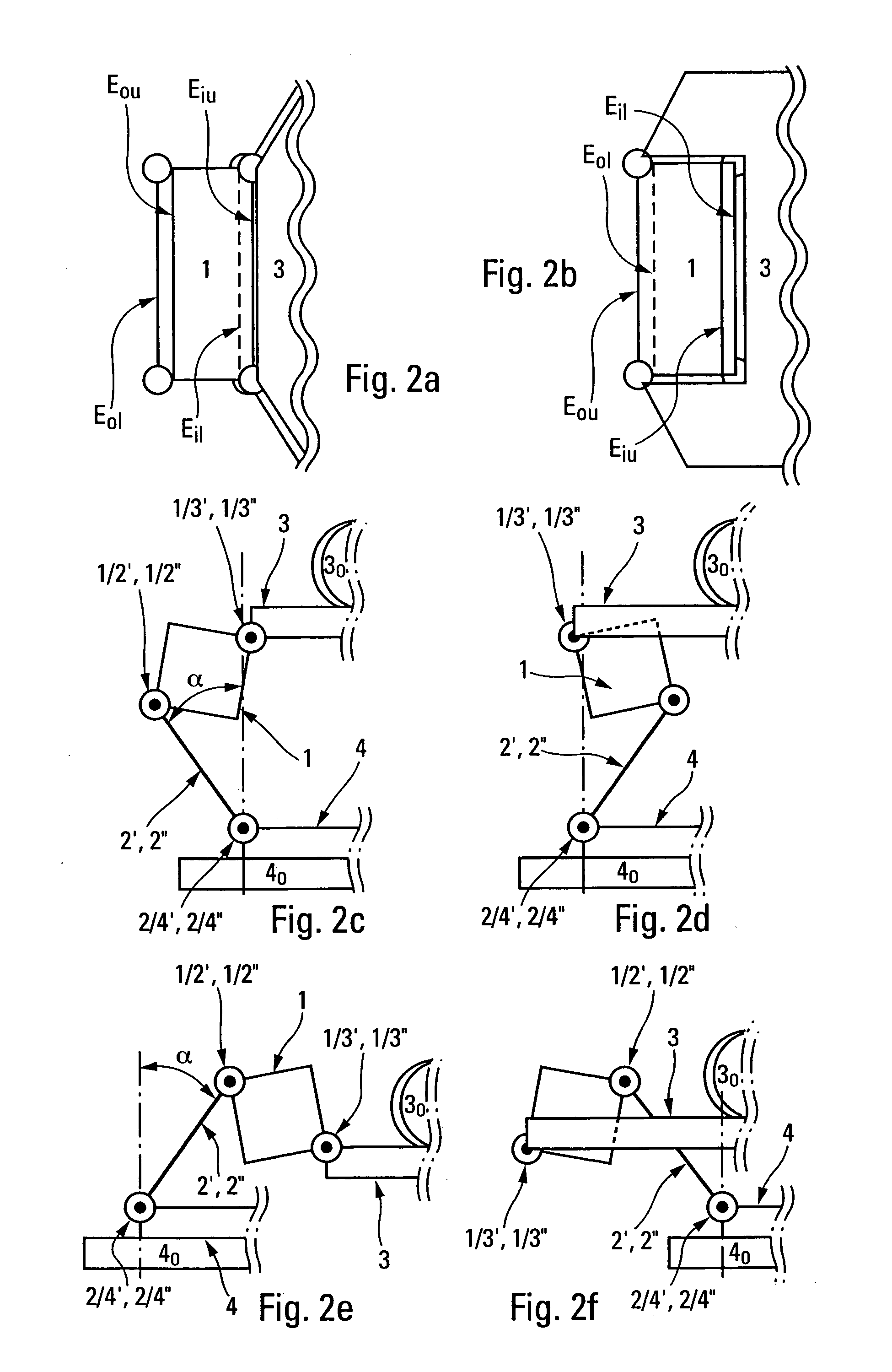
[0078] In this second embodiment, the means for linking 2′1, 2″1, 2′2, 2″2, 2′3 and 2″3 are connected to the respective means for stiffening 11, 12, and 13 at the ends of their outer upper edges Eou. Moreover, the means for supporting 3 is connected to the means for stiffening 11, 12, and 13 at the ends of their inner lower edges Eil.

[0079] The design of this second embodiment of the complex coupling device also incorporates ideal angles α of the arccos (sqrt (2 / 3))≈35° between the axes of the means for linking 2′1, 2″1, 2′2, 2″2, 2′3 and 2″3 of the three elementary coupling devices and the vertical direction as shown by FIG. 4d. These angles α are internal, with which is meant that the means for linking 2′1, 2″1, 2′2, 2″2, 2′3 and 2″3 of the three elementary coupling devices are ...

third embodiment

[0083]FIGS. 5a, 5b, 5c and 5d present the complex coupling device. This embodiment comprises three non-rotating box-shaped antennae 61, 62, and 63, which are rigidly connected in a highly integrated manner to the means for supporting 31, 32 and 33.

[0084] The third embodiment of the complex coupling device proposes to connect the means for linking 2′1, 2″1, 2′2, 2″2, 2′3, and 2″3 to the respective means for stiffening 11, 12, and 13 at the ends of their outer lower edges Eol. Moreover, the means for supporting 31, 32 and 33 are connected to the respective means for stiffening 11, 12, and 13 at the ends of their inner upper edges Eiu.

[0085] As clearly shown in FIG. 5a, FIG. 5b, FIG. 5c and FIG. 5d the third embodiment of the complex coupling device comprises six means for absorbing vibrations and shocks 5′1, 5″2, 5′2, 5″2, 5′3 and 5″3, materialised as, for example, wire rope isolators (cable mounts).

[0086] The means for absorbing vibrations and shocks 5′1, 5′2 and 5′3 are placed und...


PUM


Abstract

This invention relates to elementary and complex coupling devices. In particular, such coupling devices may be used for supporting radar, antenna or optical sensor equipment, notably on vessels. The invention is an elementary coupling device comprising a means for stiffening the elementary coupling device against torsion. Means are provided for linking the stiffening means for stiffening to a second object to be coupled. First hinging means for hinging each linking means directly or indirectly on the second object to be coupled at two separate points. Two second hinging means for hinging the means for stiffening on each means for linking at two separate points. Hinging means for hinging the stiffening means are provided directly or indirectly on a first object to be coupled at two separate points. A complex coupling device comprising three of these elementary coupling devices.

Description

BACKGROUND OF THE INVENTION [0001] 1. Field of the Invention [0002] This invention relates to elementary and complex coupling devices. In particular, such coupling devices may be used for supporting radar or antenna or optical sensor equipment, notably on vessels. [0003] The first aim of such coupling devices is to adjust one object in relation to another. Therefore, the first art has used straight adjusting means having no interconnection with each other. [0004] Owing to this straightness, it is impossible to adjust one object to the other giving simultaneous retraction, extension, lateral and tilting movement. [0005] 2. Discussion of the Background [0006] Present coupling devices are designed to permit mutual translational movement and prevent mutual rotation of the objects as the one proposed by the American Patent U.S. Pat. No. 3,871,778 granted Mar. 18, 1975. [0007] This patented coupling mechanism couples the objects by elastic means and by means of at least three coupling dev...

Claims


Application Information

Patent Timeline
Patent Type & Authority Applications(United States)
IPC IPC(8): F16F15/00F16B1/00F16F15/02F16M11/12H01Q1/00H01Q1/12
CPCF16F15/02F16F2230/0052F16M11/046H01Q1/1207F16M11/125F16M2200/041H01Q1/005F16M11/12
Inventor MULDER, JAN
Owner THALES NEDERLAND BV
Why Eureka
Try Eureka