

Adaptor for reducing EMI
- Summary
- Abstract
- Description
- Claims
- Application Information
AI Technical Summary
Benefits of technology
Problems solved by technology
Method used
Image

Examples
Embodiment Construction
[0015] While the invention may be susceptible to embodiment in different forms, there is shown in the drawings, and herein will be described in detail, specific embodiments with the understanding that the present disclosure is to be considered an exemplification of the principles of the invention, and is not intended to limit the invention to that as illustrated and described herein.
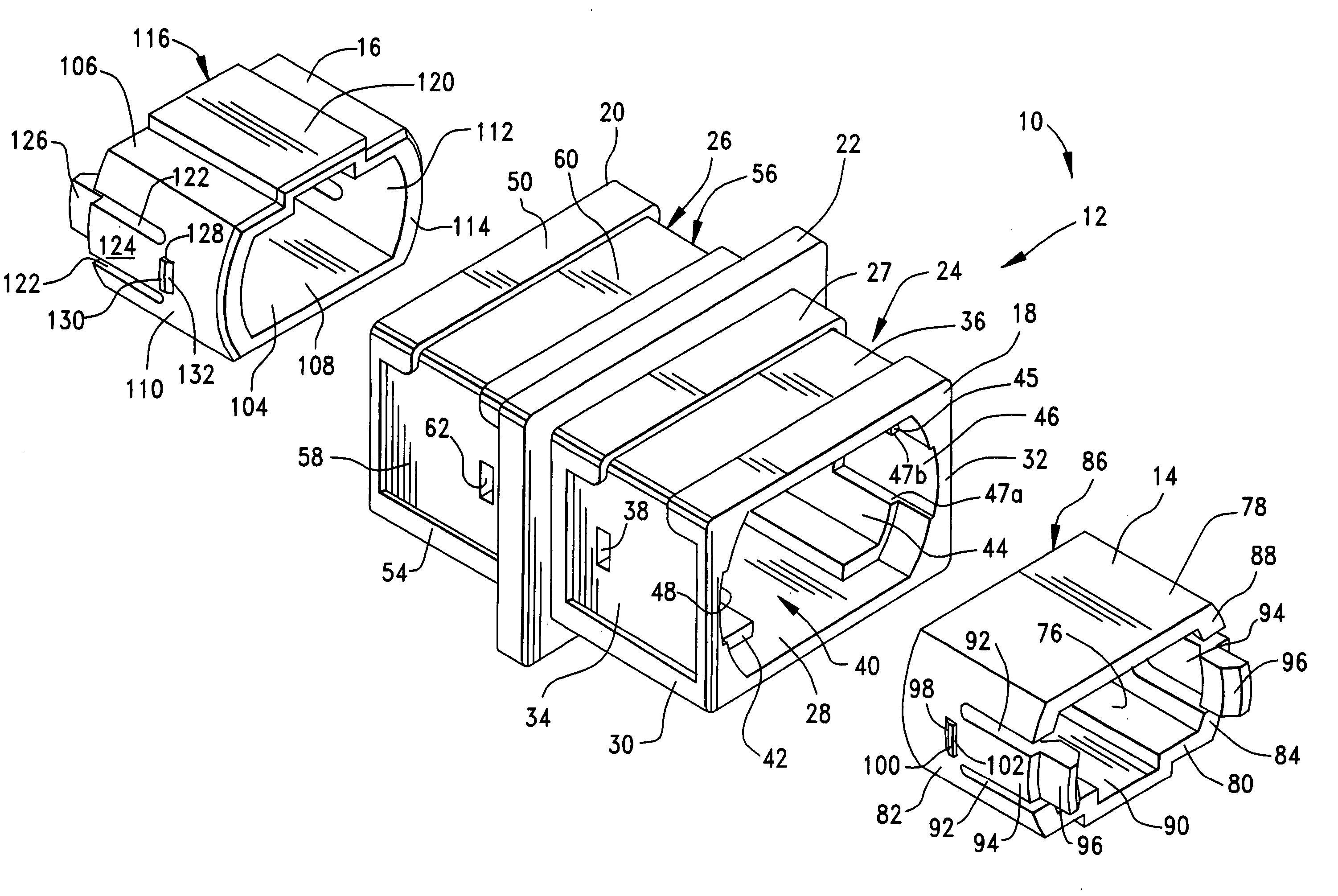
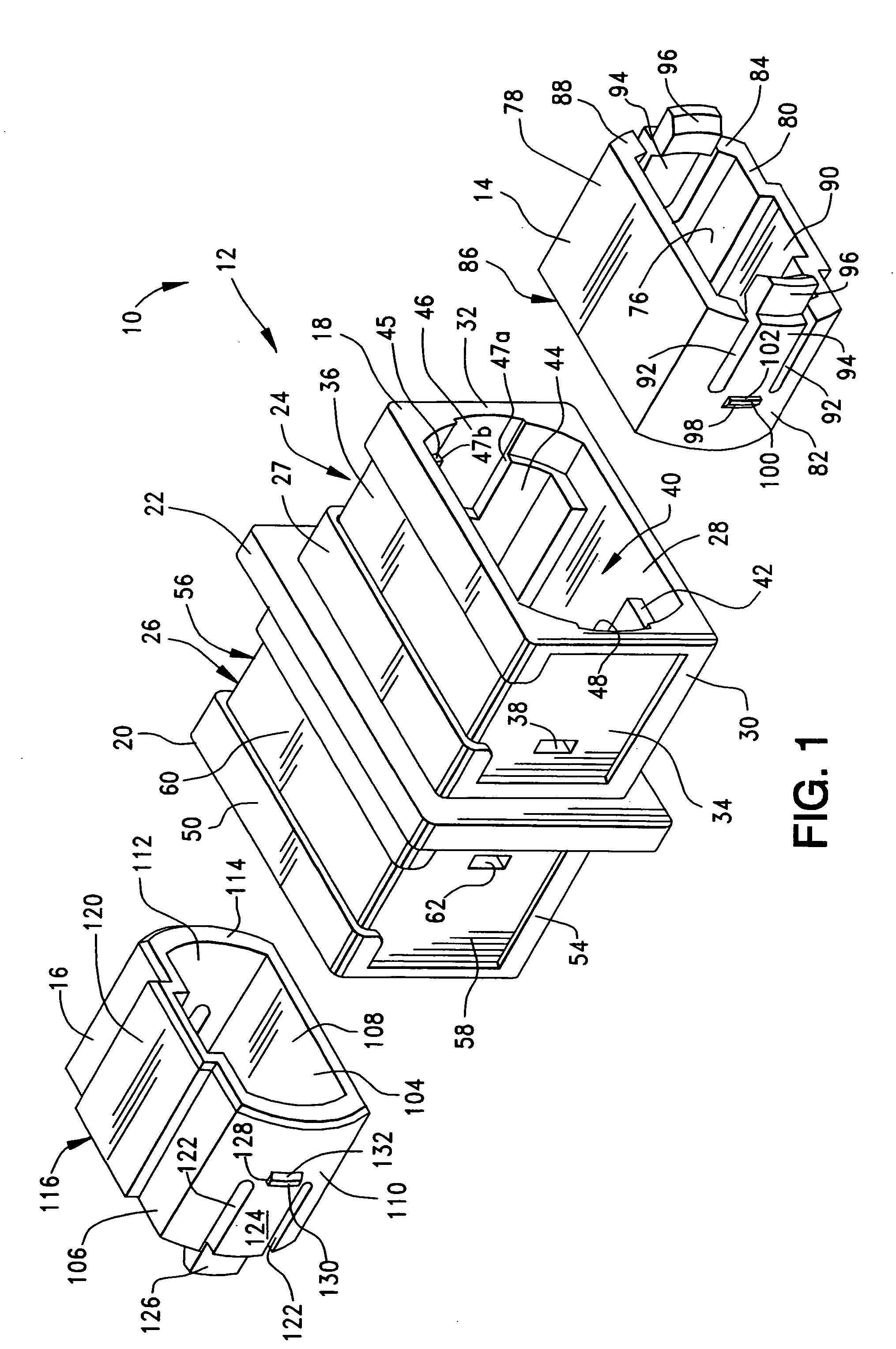
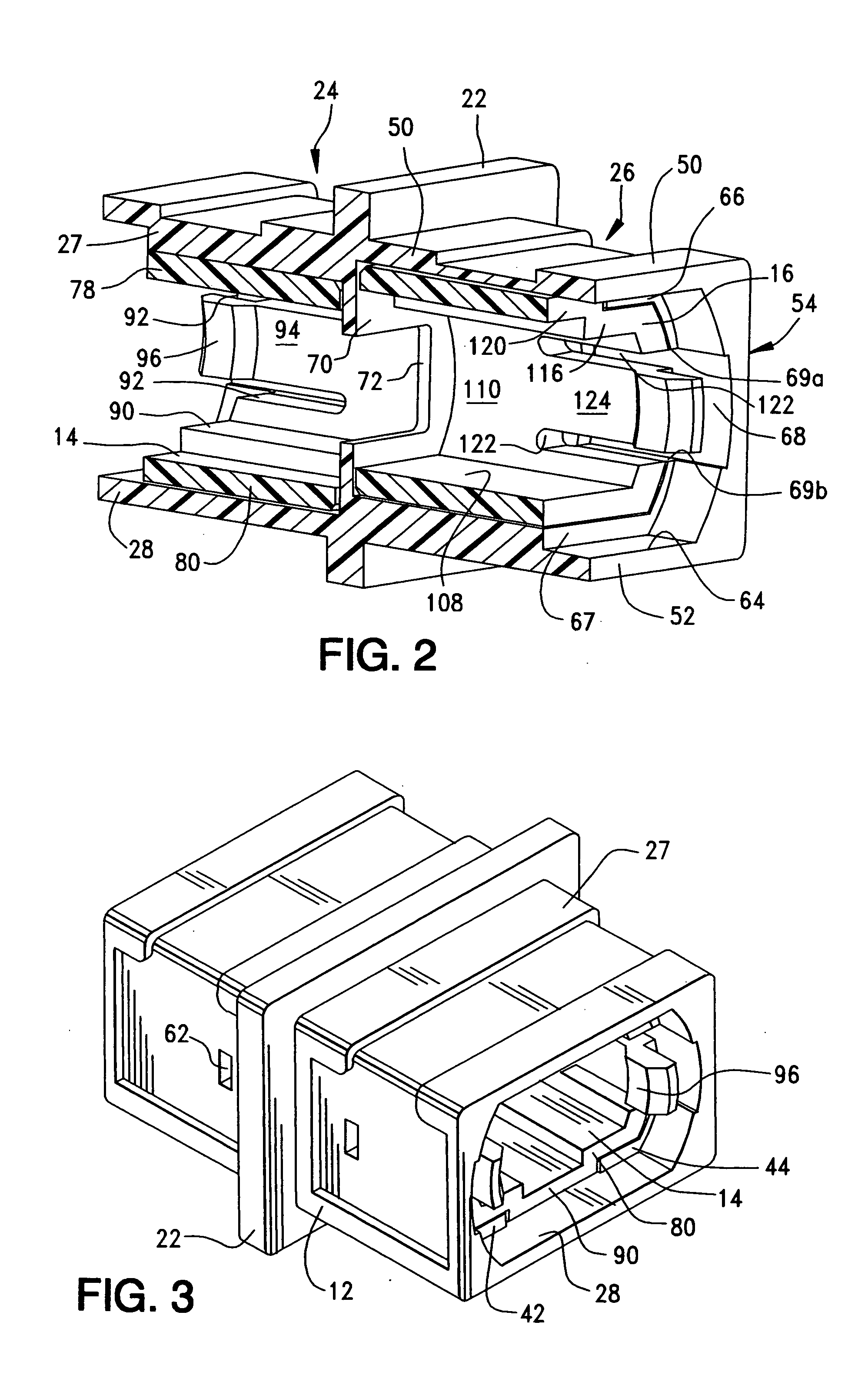
[0016] The adaptor of the present invention is used to mate two fiber optic cables. A first embodiment of the adaptor is shown in FIGS. 1-3. A second embodiment of the adaptor is shown in FIG. 4.
[0017] The adaptor 10 generally includes a central housing 12, a first latch 14 which mates with the central housing 12 and a second latch 16 which mates with the central housing 12.
[0018] The central housing 12 is a unitary piece and is generally rectangular in shape. The central housing 12 is formed from metal and preferably the central housing 12 is formed from diecasted metal. Because the central housing 1...
PUM
 Abstract
Description
Claims
Application Information